If you find yourself wondering where in the world you are going to put all those switches for your electronics without making a huge mess, this may be an option. There are plenty of great write-ups on this age old TJ mod and probably even more poor ones. Here I will cover the basics and show a couple things I haven’t seen mentioned before.
First thing is to find another switch panel. I found mine at [email protected] or you can find them on facebook, TJKparts. They only handle TJ parts at this time and last time, I snooped their racks of parts they had a small pile of these stock switch panels.
Tools: Dremel, safety glasses, hearing protection, utility knife, basic hand tools, blow torch, nail and a pile of nachos…
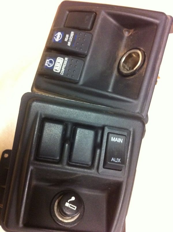
I decided that I wanted my ARB switches and all the AW-4 transmission control switches in the new location. Previously the ARB equipment was controlled in a dash top pod that also houses my mechanical gauges.
The first thing I noticed whilst testing out fitment on the switches was that they are nearly impossible to remove once you have them shoved in there. It can be done but at risk of impaling yourself with a tool when trying to release tabs and pry them loose.
just sayin…
Time to get the center bezel off and getting stuff ready. I really wish I had more pictures but I will explain…
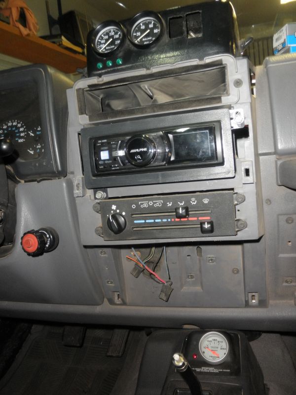
First, take the dashboard top trim off by grasping the edge near the windshield and rolling it back towards you. It just pops into place as there aren’t any screws. The center bezel has three screws holding in place, two on top and one behind the ash tray.
You can now pull the bezel off toward you. It also has spring clips holding it in place. On my TJ, the spring clips are the only thing that hold my bezel because of the gauge pod mounted where the sunglass tray used to be.
The ash tray support assembly will have to be cut out of the center bezel. I cut it and left extra material the first time just to get it out of the way and later went back and copied what the driver’s side looked like. Test fit along the way and it should work out. This is a step I suggest saving for near completion as it is one of the last things to go back on.
Okay, we have to find a way to get these babies together, right?
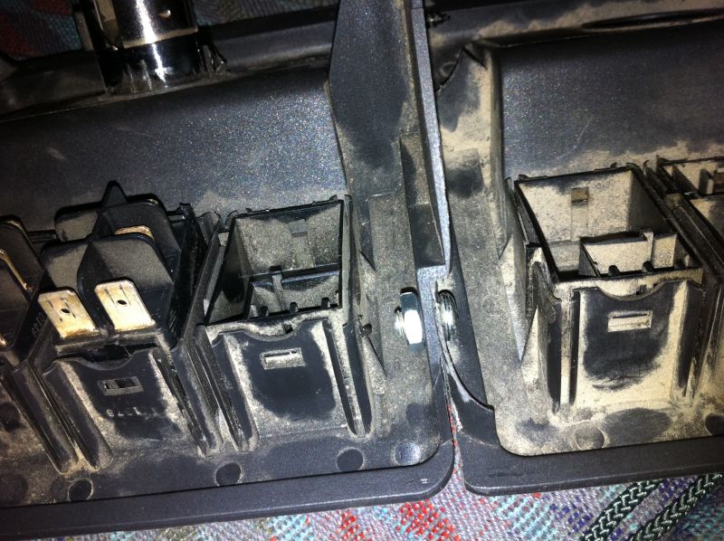
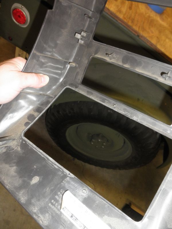
First of all, we don’t cut the original one. It is going to support the left side of the new switch panel. Look at the right side of the original panel and you will see two triangular recesses and a narrow recess that connects the two top to bottom. (why didn’t I take a pic?)
What you should aim to do is make a template of this area and use it to cut the left side of the new panel to match. Neatness counts as this is all part of the support for the whole thing. The better the fit here, the better everything turns out.
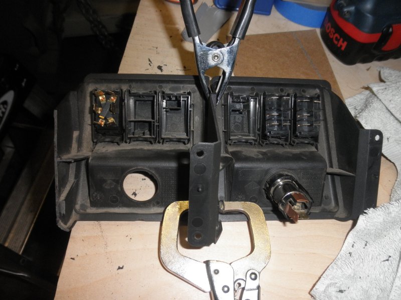
In order to test fit everything I used some clamps to help me keep it all together so I could see what needed to be done. While you have it clamped together you may notice that on the left edge of the new switch panel the edge flares out some. This I sanded back with a barrel attachment on the Dremel tool. I was almost able to get the top wedge shaped reveal to match the bottom.
I am sure there are lots ways to do this step. As you can see, I bolted this together. You are not going to get a drill bit in there too easily so what I did was heat up a bent nail, made it red hot and melted the holes as needed. It really worked well.
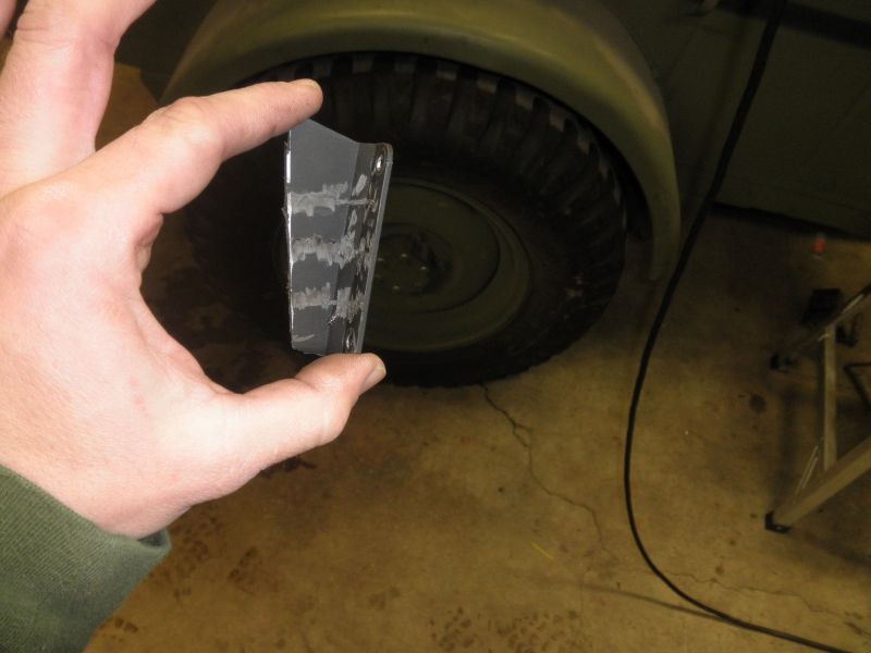
While test fitting you will notice there is no way this thing is going to fit without chopping something else off… This is the part in the way but don’t throw it out just yet as it will go back on again.
Measure the best as you can to decide where to cut, adjust the alignment of your switch panel and when it’s how you like it, screw the angled piece back on to support the right end of the assembly. I saw in another good write-up the use of the folded blind nut that will slide into a slot and give the screw a firm bite. I will be looking for some of these for my own project.
More Switch Panel
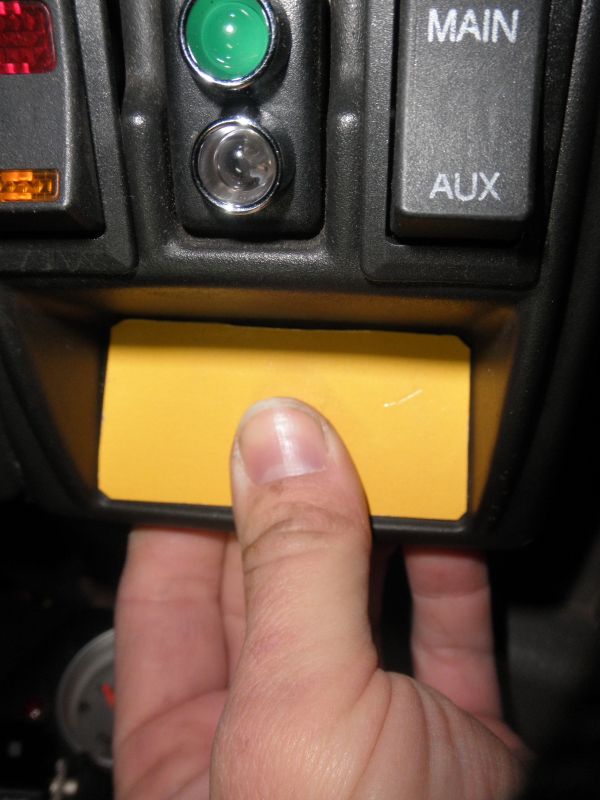
I didn�t like the big hole left behind by the cigar lighter (it didn�t fit anyhow) plus, I wanted to gather all transmission controls in one place. This is a thin piece of cardboard that was used as a template. Same kind of stuff I used before while figuring out the panel mating.
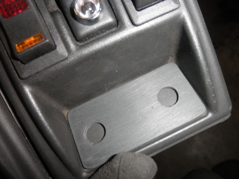
This is a piece of another ashtray from a Dodge. I wanted something light and rigid to mount the switches into. The color is very close.
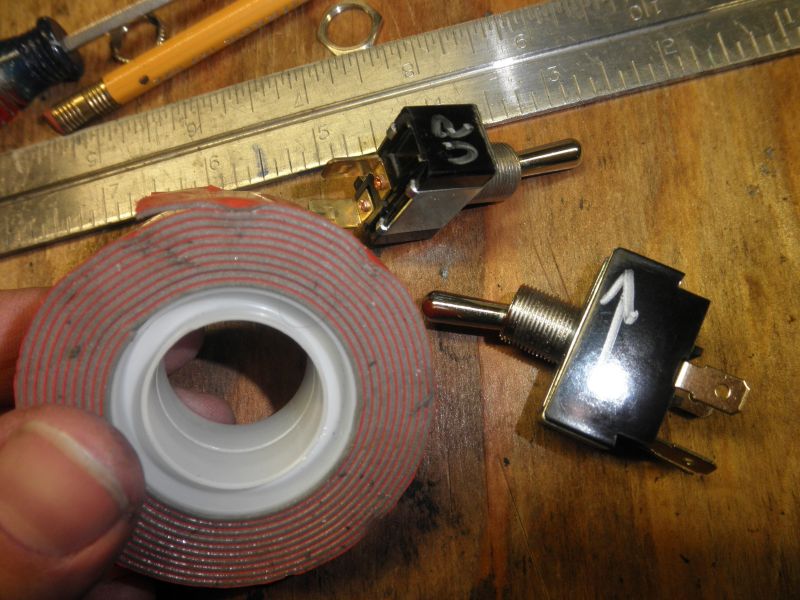
Anti-spin… Double sided tape made by 3M, it works well to help keep the switches from rotating while they live in the new panel. Not exactly needed but I like it… Also, I used a multi-meter to find which end was up for my applications and marked the switches accordingly.
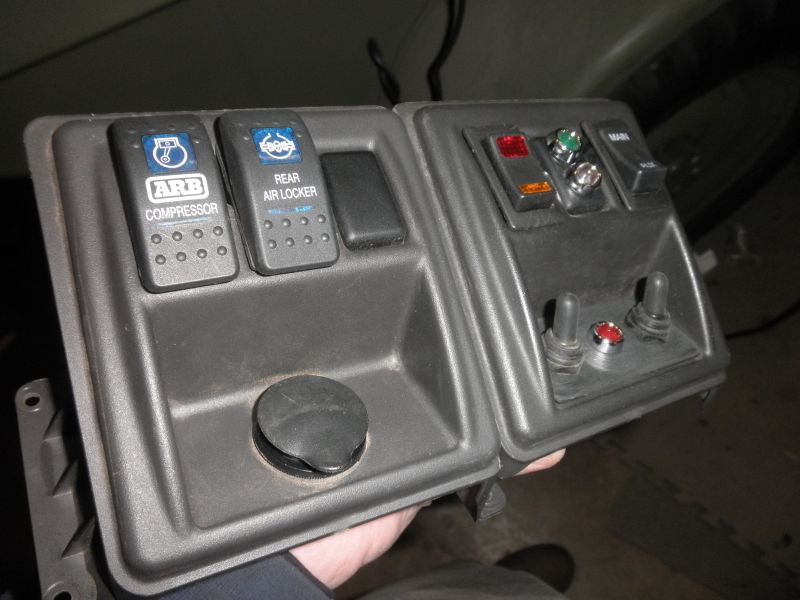
Look at that! So professional looking and sort of a pain in the butt… At this point I thought I was done with the pain part. Most of the pain came from debugging the project associated with all those wires pictured later on.
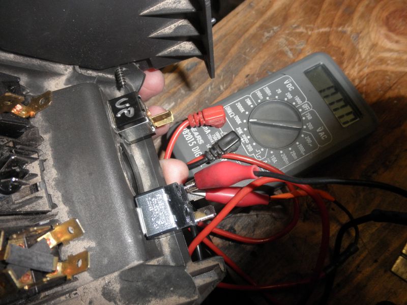
Before anything was going to get hooked up, I tested things to make sure that the switches worked properly and were installed correctly.
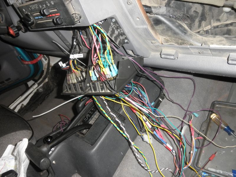
That’s a lot of wire! To make it easier to run wires to their new homes, I took a hole saw and made a 1� hole directly above the switches. It was the only way.
What you are looking at are six switches, two relays and three LED indicators. I�m not too sure if I can get anything else in there! Cutting your wire to the correct length will be helpful and route it around anything that moves behind the dashboard like the HVAC controls.
In this picture you can also see the angled plastic piece I used from left over parts. Once you get all those wires stored away you can test fit and adjust the center bezel.
Now you can fine tune your bezel as described above early on in this write-up.
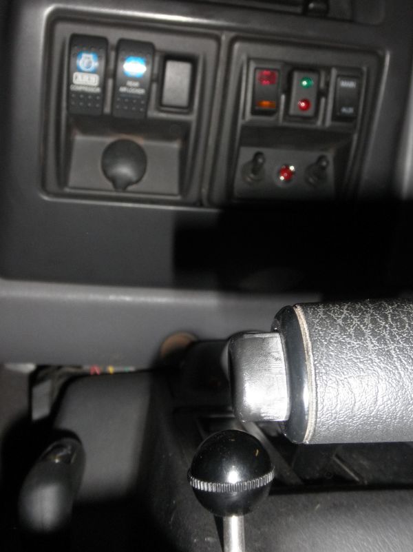
The front of the switch panel installed. Look closely at the area between the two panels and you will see how I evened up the wedge shaped left side that I mentioned above. Careful that you don�t go too thin here. If you do… That�s why they invented getting another one and trying again :0)
I was not able to get the top right screw back into the original panel because wires and relays were in the way. The bottom screw is easy to tighten with a 1/4� box end wrench.
This modification was more involved than I thought it would be at first. It will take some patience and the results will be highly individual based on said patience… The Dremel tool is a huge asset in this mod.
If you are a proud owner of this great tool you will know that although it is small, it still flings stuff everywhere. Depending on your rotary tool�s speed, some of that stuff could be molten plastic, it doesn�t taste very good in your eyeball either. Ear protection is also a good idea if you have some handy.
Jeep on!
Tim :o)