LED Flush Mount Tail Lights
The last step deals with the turn signal flasher. The TJs use a hybrid flasher, a combination of solid state circuitry and a mechanical relay. A small IC chip is used to control the relay and also monitor for a burned out flasher bulb. When a turn signal bulb goes bad, it doesn’t draw any current. The flasher senses this reduced current draw and kicks the flasher into a high speed flash mode in order to draw your attention to the problem. One of the great things about LED lamp assemblies are their reduced current draw (compared to a regular bulb). This reduced current draw is sensed by the flasher and since a regular flasher doesn’t understand anything about LEDs, it goes into high speed flash mode.
Not all vehicles have a BOB (burned out bulb) detector circuit, especially older vehicles, so LEDs will work on some vehicles without needing a flasher change.
A TJ Flasher FAQ is now available which puts most of the flasher info in one convenient place.
NOTE: The flasher circuit changed for the 2001 model year. If you have a 2001 or new TJ, then go here to get the proper modification information for your flasher.
NOTE: If you have a YJ and your flasher does not flash (just sits there with the LEDs lit up), then try a Tridon Stant EL-12 flasher in place of your existing flasher. A YJ owner said his LED lights flash perfectly after he swapped in this model flasher. You should be able to find this flasher at most any auto parts store.
NOTE: In March of 2006, I received an e-mail from RobertW, who works for Trico Electronics (the folks that make the flashers). He informed me that an update to the Trico (Tridon) EP-26 was made and it now supports rear LEDs without any modification. The EP-26 is a drop in replacement for the older TJs. Be sure the package says LED on it so you know you have the new model and not old inventory from the auto parts warehouse. Thank you Robert for the very good news!
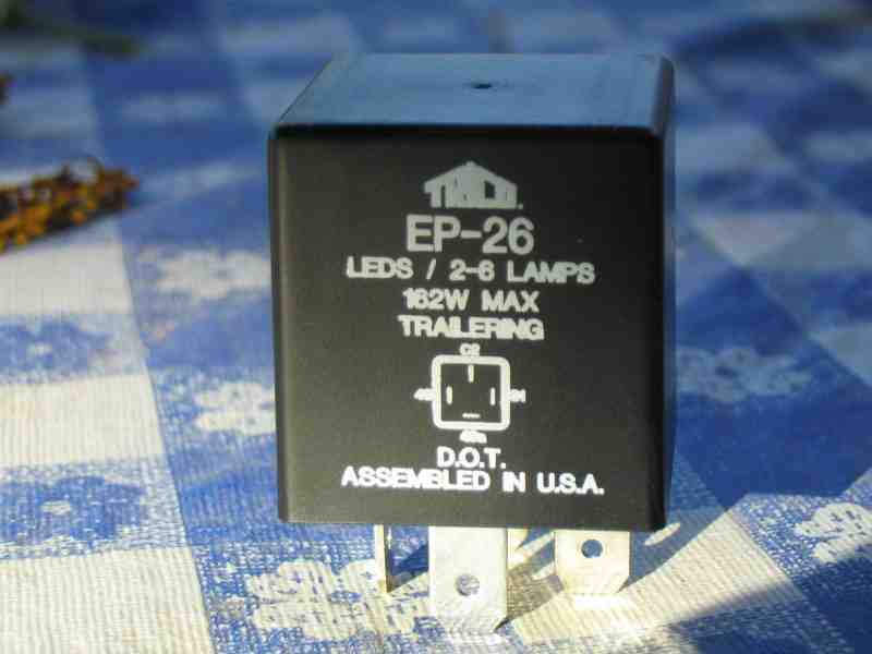
I’ve included a photo of it here since so many people have asked me about it. And I made it larger than my usual photos so you can read the info on the flasher itself.
Note: 4/7/2006 – A local Jeeper located one of the new EP-26 flashers and installed it into his ’98 TJ. It worked perfectly with his LED rear lights and there were no mods done to the flasher. Thanks Trico! (and thanks to RobertW for the heads up on this helpful information)
This fix, for the flasher, is not of my own discovery. I can not take credit for it. I dug up the details for doing it on the web as it was explained by sbessel (JU screen name). The alternative to using this flasher modification is to use some BIG heat generating power resistors in your wiring. OUCH! Not me….sorry folks…I do NOT want or need any 20 watt space heaters trying to melt my wiring harness.
NOTE: Since writing this article, I have received e-mail from a person who decided to switch over to this flasher method. He was using the power resistor method. He told me in his e-mail that the tape and some of the insulation was in fact melted by the heat given off by the power resistors. Enough said?
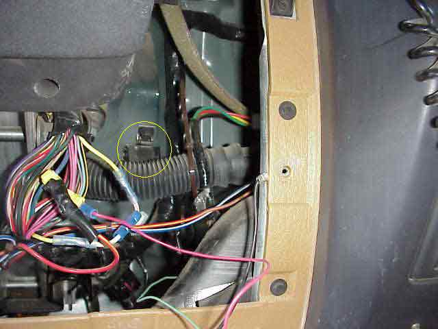
Remove the plastic panel beneath the steer column (two screws) and then the metal panel (4 screws). Doing this will give you easy access to the turn signal flasher. The flasher is tucked up out of the way (kind of hard to get to) and is circled in yellow in the above picture. Pay no attention to the extra wiring in the above photo…..it has nothing to do with this project. The flasher’s connector is pulled off (no locks on it) and then the flasher can be pried out of its metal mounting clip. If you can’t get it out of the clip, just unbolt the clip (and flasher) and take it out.
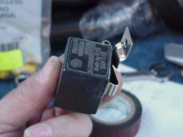
Here is the flasher and metal mounting bracket. I have unclipped one side of the bracket. When I put everything back under the dash, I bolted the metal bracket in place and then popped the flasher into the bracket. Once you have it in your hand, you will quickly see how it works (assuming my comments here are not making any sense).
There are three tabs on the bottom of my flasher that held the guts inside the shell. I used a small screwdriver to pry the tabs away from the body of the flasher so that the insides could then slide out of the case.
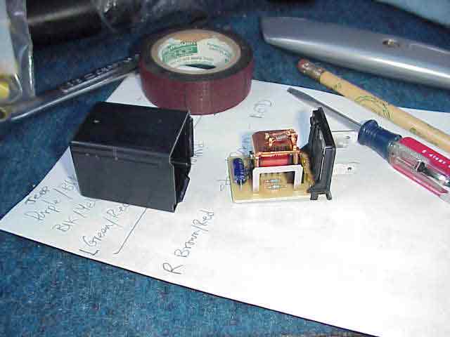
Here is the flasher assembly, with the guts carefully removed from the housing. The circuit board, which is attached to the base of the flasher assembly, contains the relay and the relay control circuitry.
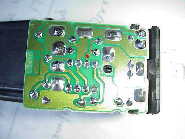
Here is the bottom of the circuit board. I have put a small RED dot (in the pic above) on the circuit run that you must cut. Take a sharp, small knife (an Exacto knife works well, or a single edged razor blade) and carefully cut the metal foil at the red dot. I made two parallel cuts, about a 1/32″ of an inch apart and then carefully scraped the material away that was between them. By cutting this circuit run, you disable the burned out bulb detector circuit in the flasher assembly. This will allow your new LED lights to flash at the near normal rate.
I wanted to make sure my cut run was done properly before I put everything back together. So, I carefully plugged the flasher (without the cover) into the wiring harness, making sure it DID NOT TOUCH anything else under the dash. Turn on the ignition switch and then your turn signal. A successful operation will be rewarded with a normally functioning flasher. If it still flashes very fast, you didn’t get the circuit run cut and will need to remove the flasher and check it.
Once you are satisfied that you have modified the flasher, pop the guts back into the case and install the flasher assembly back under the dash. Replace the metal and plastic panels under the steering column, pat yourself on the back, and tell yourself congratulations for a job well done!
Just in case you are nervous about cutting open your good flasher, you can buy a replacement flasher at the local autoparts store so that you have a “hot spare”, just in case you go crazy and smash it all up! (just kidding). A Triden Stant EP26 is a directly replacement for the factory flasher and it is believed that this company makes the OEM flasher used by Chrysler.
That is about it. You now are the proud owner of a cool looking set of LED tail lights.
Again, I want to thank Dirk at DPG Off-Road for the assistance in making this project happen. Give him a call and tell him you want a pair of those good looking LEDs…..just like the ones I installed.
Update:
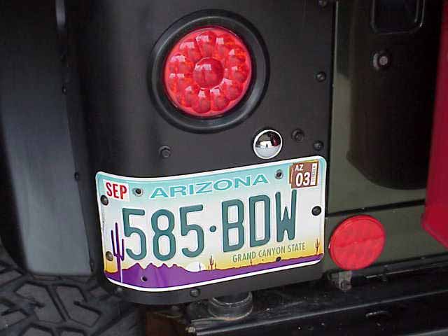 As for the license plate lighting, I picked up a $2 light at AutoZone and tapped it into the tail light wire going to the LED assembly. So, I now have legal lighting on my license plate. This simple task turned into an hour project. The package the light came in states that it snaps into a 1″ hole. I stopped at my local Ace Hardware to get some Grade 8 bolts and remembered to pick up a 1″ metal cutting hole saw. I drilled the hole and went to pop the light into place…..oops….seems it takes a hole about a 1/4″ bigger than what I had made. So much for instructions on the back of the package. Oh well, what can I expect for $2….at least the light lit up when I tried it.
Remember…..TREADLightly!
The 2001 and newer model TJs also use a hybrid flasher circuit just like the pre-2001 models. However, DC decided that the previous design needed a change and so the IC chip in the flasher was swapped to a different (but similar) model. This rendered the previous flasher mod as null and void.
NOTE: If you want a drop in replacement flasher, with no modifications necessary by you, then you will want to to see this new flasher available from Mark Lochridge of Gold Coast Distributing Co.
If you wish to attempt a modification to your factory flasher, continue reading this write-up. Many thanks to Jeepin’ Geo on JU for the pics and information. He was very supportive in allowing me to post the pics and info here so as to provide the readers with info for the newer TJs.
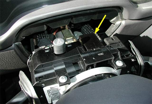
Here is the location of the flasher relay in the 2001 and newer vehicles. Note that it is now located on top of the steering column instead of below it as in the older models.
Since I have not taken this version of the flasher apart, I will assume that its case is held on in the same manner as the older model. If so, then there are three tabs on the bottom of the flasher that holds the guts inside the shell. Use a small screwdriver to pry the tabs away from the body of the flasher so that the insides can slide out of the case.
Unlike the earlier models, this flasher’s lamp out detector circuit can not be bypassed by simply cutting the circuit run. Instead, you must install a small relay which effectively bypasses this part of the circuit and allows the flasher to function at the normal (and desired) flashing rate. The relay can be obtained from Radio Shaft, part # 275-241. It is small enough to fit piggy back in the flasher module and you will be reinstall the cover once you are done.
To make all of this happen, you will need to be comfortable with a soldering iron….and I don’t mean one of those big 3000 watt flame throwers that I’ve seen some folks claim are soldering irons (yeah, right!). It you are outside of your comfort zone at this point, then I suggest you find a friend who can do this for you. It is not overly difficult, but there is no reason to burn up a perfectly good flasher while you attempt to learn how to solder.
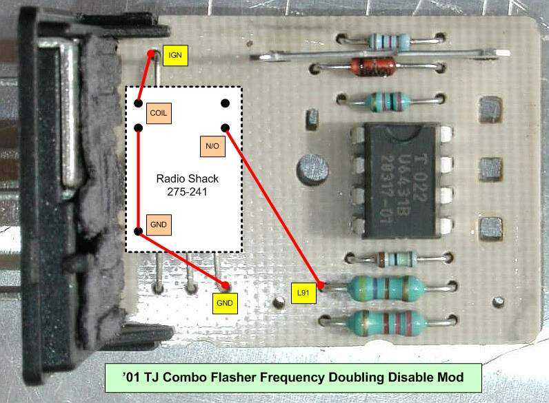
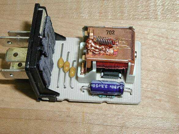
To make things a bit easier to see, the flasher relay was removed from the module in this picture. You should not have to do this in order to make the 3 wiring connection to the circuit board. Note that there is also one jumper connection on the Radio Shack relay itself, between one of the coil contacts and the ground pin. Don’t forget to do this one too or else you won’t get the results you are expecting.
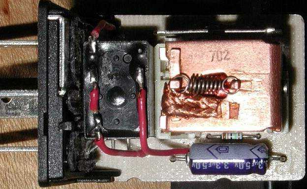
Here is the complete flasher module with the flasher relay back in place AND the Radio Shack relay that has been connected via the red wires. Once the Radio Shack relay has been installed, slip the flasher module back into its socket and try it out (I would probably not put the module cover back into place until I’ve had a chance to test the flasher module in the Jeep….just be careful when you test it and make sure it does not touch anything while the cover is removed).
When everything checks out OK, reinstall the cover, put the flasher module back into the socket, and test it one more time. If all is still a go, then put the dash back together and wrap up the project. You are good to go at this point.
I hope you enjoy your new LED tail lights as well as your flasher mod.
Remember…..TREADLightly!