Changing you air filter is a very easy job and one that you can do in just a couple of minutes. It is important to keep your air filter in good condition. A dirty filter will restrict air flow to your engine and cause poor performance and gas mileage.
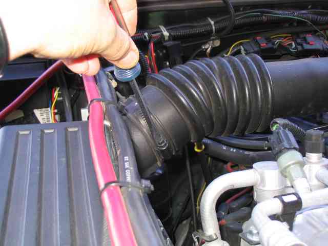
The air filter is located inside of the air cleaner box. Depending on which year your Jeep was made, the air cleaner box is located in different spots in the engine compartment. On mine, it is bolted to the passenger side fender well. I have to remove the breather tube from the air filter box cover. This is done with a screwdriver. Once the screw is loosened, I pull the tube off of the air cleaner box.
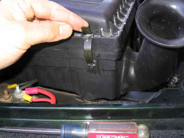
The cover of the air cleaner box is held in position with a half dozen spring clips. The clips much be released for the cover to be removed. Sometimes a screw driver is useful in releasing the clips. Once the clips are released, the cover can be lifted from the air cleaner box.
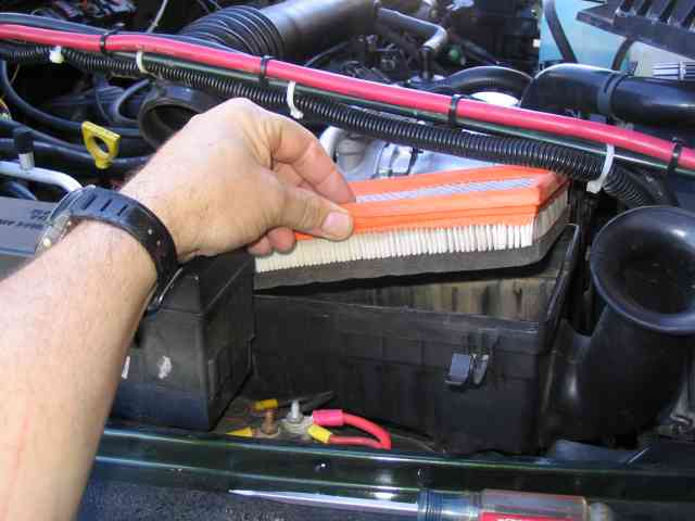
The filter sits in the top of the air cleaner box. Lift it out to inspect the filter and/or replace it. Reverse the above steps to install the new filter and restore the air cleaner box to normal.
AW-4 Transmission Swap
Well, it finally got to be time to swap out the manual AX-15 transmission and install an automatic transmission. Unlike some tranny swaps done by others, I did mine because I could, not because I had to. My AX-15 is running strong with no signs of trouble. I opted for the AW-4 automatic that is commonly found in the Jeep Cherokee. This tranny has seen hard use by the local XJ owners and I haven’t heard them complaining about it. Although Scott Kruize sold his AW-4 equipped TJ, I know the current owner and it is still running strong. I wanted a tranny with an overdrive so the three speed auto that was available in ’98 TJs wasn’t really in the running. Besides all that, finding an AW-4 tranny would be much easier due to the plethora of automatic equipped XJs. Many a soccer Mom’s XJ has met with early retirement directly after a traffic accident.
I am putting this first part of the write-up together prior to doing the swap. There is plenty of stuff to document before the first bolt gets turned. I’ve spoken to Bob, the current owners of Scott’s TJ, and if his schedule allows, he plans to help me wrench on mine. Bob is a good friend and we’ve managed to do some fun trails together over the past couple of years. If he can plumb the AW-4 cooling lines as well as he drives, I’ll have it made!
A few other thinks to take care of while I am thinking of them….the thank you part. A big thanks to Troy at Toys by Troy. Troy was kind enough to lend me some lift time in his shop so I didn’t have to lay on my back on my driveway. While it is certainly possible to do it with all 4 tires on the ground (that is how Scott’s was done), standing under the vehicle during a project like this does have its advantages. He also arranged for a price on the tranny that I would not have normally gotten. Troy, thank you very much for your assistance on this project.
Another thank you goes to Nacho at AMC 4×4 Salvage. He gathered together all of the pieces and parts and provided me with a very low mileage ’01 AW-4 tranny. He put up with my typical 101 questions and still kept smiling. The real test of his Jeep prowess will be when the TJ bracket I ordered at the Jeep dealership arrives and his XJ shifter fits in it. If that all goes inside my console without the need to break out the SawsAll, my hat goes off to you! Thanks for making it all come together.
With that out of the way, let’s get down to business….first, I’ll run through the parts I picked up.
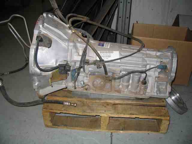
Here is the main piece of the project, the AW-4 transmission. It had a bunch of dust on it, but not a single drop of fluid on the external surface. If I remember correctly, Nacho said it has less than 10K miles on it before the donor XJ was in an accident and totaled. Nacho also said that ’98 to ’01 XJs were the desired years for the TJ swaps. Thanks goes out to another Jeeper who did this swap. He told me that after some research, he discovered that the pre-’98 XJ AW-4 only had a single pulse output on the speed sensor while the ’98 – ’01 had a 4 pulse output. The 4 pulse version is needed to work properly….at least for the wiring method ScottK and I used.
The AW-4 has evolved slightly over time, but it is pretty much the same tranny that was first made available in the Cherokee. It has a small TCU (transmission computer unit) or tranny computer which provides electronic control for the transmission. Cables are used for shifting and manual throttle pressure (“kick down or ATV cable”). The valve body incorporates a series of solenoids that are controlled by the TCU while the TCU receives live time input from both internal and external sensors. 4th gear is a .70:1 over drive and the transmission uses a lock-up torque converter.
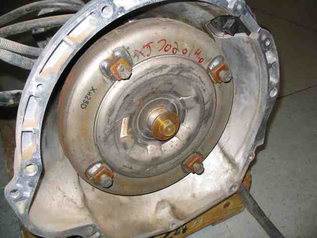
Until I get some seat time with the new tranny in place, I could think of no reason to swap out the stock torque converter for one with different specs. Besides that, I’m still reading up on stall speeds and all that other stuff that manual tranny folks never thought about. <grin> You can see the torque converter in the above photo. Those 4 mounting bolts transfer power from the engine into the transmission.
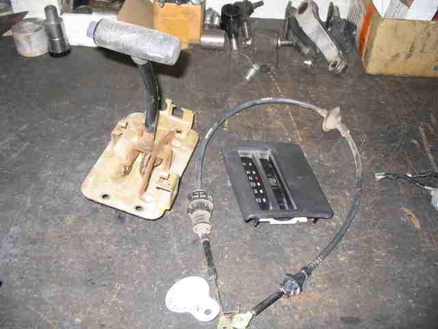
Here is an XJ shifter (on the left), the shift cable, and the shifter’s indicator panel (P,R,N,D,3,1&2). The shifter and shift cable came out of a ’98 XJ, not that it matters much. They are all pretty much the same from what I have seen. The XJ indicator panel just happens to be the same size as the opening in the TJ’s console, so it will pop right into position when the time comes.
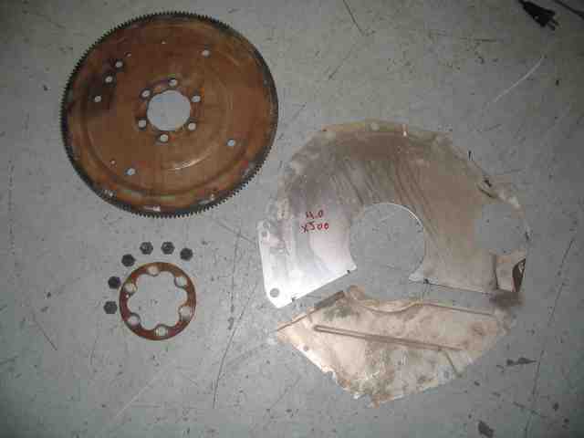
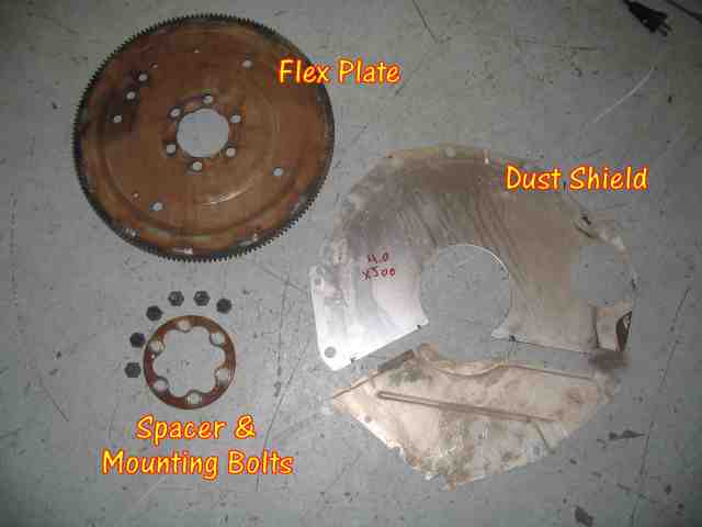
In the above picture, the flex plate is in the upper left corner. The flex plate for most automatic transmissions is simply a stamped-steel disc with a ring gear located at the outer edge for engagement with the starter’s pinion gear. In the above photo, the 6 bolts and ring (shown directly below the flex plate) fasten the flex plate to the engine’s crank shaft hub. Those 4 bolts on the torque converter match up with 4 of those holes in the flex plate. The dust shield is shown on the right side of the photo. It installs between the engine and the transmission.
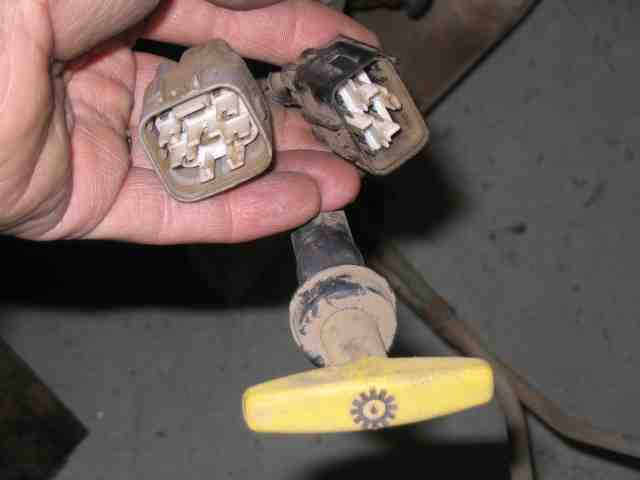
There are two cable harnesses attached to the transmission. They provide control of the shifting solenoids and also tell the TCU what position you have selected with the shifter. In the above photo, you can see the two connectors (transmission side) on the ends of the cables. They are both 8 pin connectors but are not the same design. You will see references to them in the write-up as the “gray and black plugs”.
AW-4 Transmission Swap
It was T-Day….transmission swap day….and I was about as ready as I was ever going to be. I drove to Troy’s shop and got ready to start the swap. Bob was scheduled to join me and help for a couple of days. He showed up just a bit after I got started removing the center console.
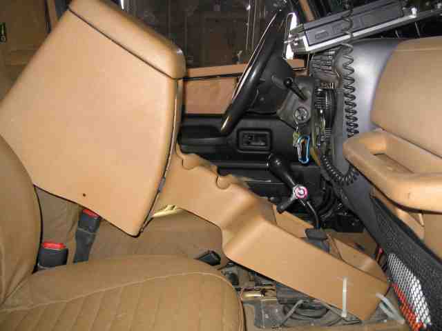
The center console is held in place with about 6 screws, give or take one. A couple of them are accessible by opening the cover (and removing ALL of your junk). Another is in the bottom of a cup holder slot while there are two more along the rear of the consoler (passenger side). The plate that the shift boot attaches to can be “popped” out of the console and when you do, you’ll see another screw there. You’ll not be using the boot when the AW-4 is installed so don’t worry about removing it from the shifter.
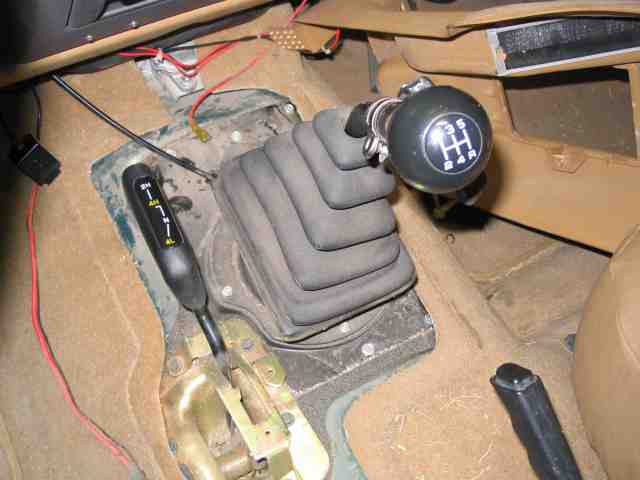
With the console removed, remove the 3 screws that hold the shifter boot onto its mounting plate. At the same time, you can remove all of the screws around the edge of the mounting plate that hold it to the body. Many of them are hidden under the carpeting.
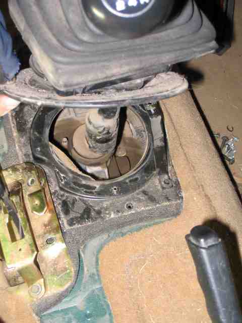
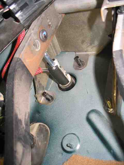
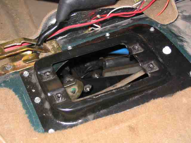
Pry the shifter boot off of the mounting plate (it is most likely stuck in place). Reach down to where the shifter enters the tranny and slide the dust cover (rubber boot) up the shifter shaft. You will see spring loaded retaining collar under the dust cover. Using a pair of screwdrivers, press the spring loaded collar down and turn it about 30 degrees. It will pop loose and allow the shifter to be removed from the transmission.
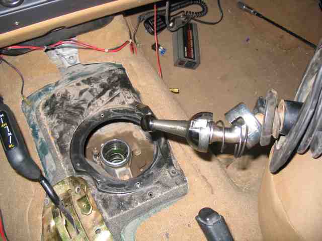
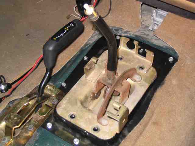
Here is what it looks like when you remove the shifter from the top of the transmission. Pretty easy way to get it out of the way without removing a bunch of bolts, eah?
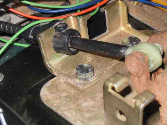
A closeup shot of the spring loaded retainer and its dust cover. You can see the notch in it. This is what you had to rotate (about 30 degrees) to get it to disengage from the top of the transmission. If you look in the previous photo, you can see these near the end of the shifter.
AW-4 Transmission Swap
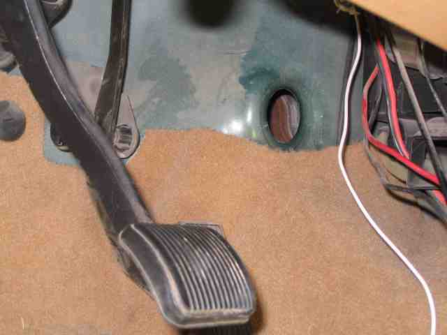
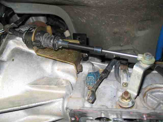
Since you are still inside the vehicle, you might as well grab a light and a wrench and remove the two nuts from the studs of the clutch master cylinder. Tucked up underneath the dash near the top of the clutch pedal, you will see where the linkage attaches to the pedal. It has some sort of crazy retainer bushing. After spending too much time trying to remove it, we separated the linkage from the clutch pedal with a small pry bar. You will also notice that the linkage has a sliding/spring loaded device on it. This sends clutch pedal position to the PCM. If you check closely, you will see that it has a couple of wires coming off of it. Follow the wires to a connector where you can disconnect them from the vehicle harness. When this is done, remove the master cylinder from the firewall.
Located on the bell housing, driver’s side, you will find the clutch slave cylinder. It too is held in place with two nuts. Remove them and the slave cylinder can be detached from the bell housing. Note that the master and slave cylinders are connected together via a hard plastic line. There is NO reason to separate the master and slave cylinders from each other. Doing so can cause issues and will result in the cylinders needing to be bled before they can be used. Keeping them sealed eliminates this and makes for a good used component that you can sell.
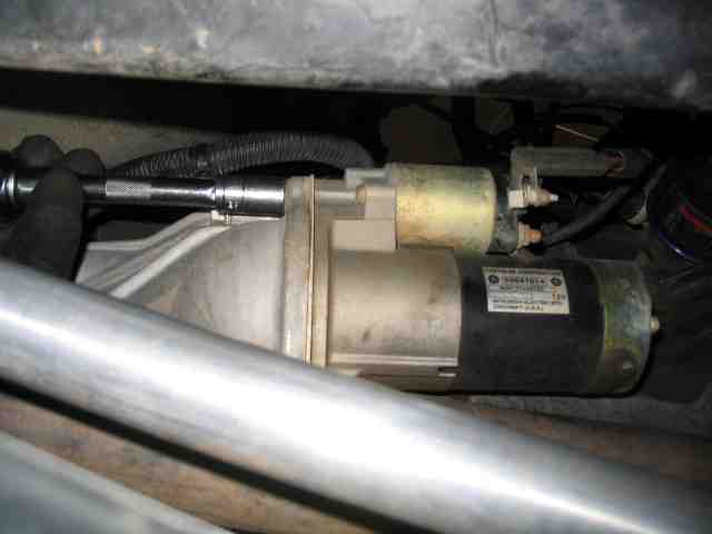
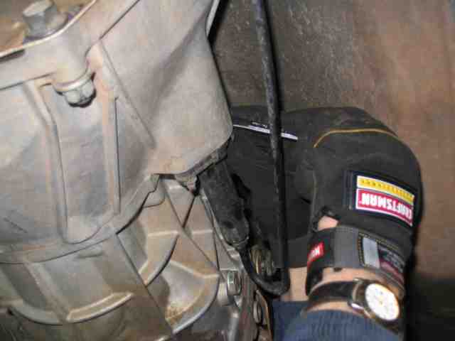
We disconnected the cable(s) from the negative terminal of the battery and then removed the two bolts holding the starter in place.
At this point, most of the major components had been removed from the bell housing. The throttle position sensor (TPS) was removed along with the front and rear drive shafts. The transfer case has linkage going to it and this needs to be removed as does that same part of the linkage that is bracketed off of the transmission.
The nuts holding the tranny mounting plate to the transfer case skid were removed and the tail shaft of the transfer case was supported. At this point, the transfer case skid mounting bolts were removed. Some other items to be removed include the speed sensor electrical connector at the back of the transfer case and the 4WD switch electrical connector on the transfer case. Check the bell housing, transmission, and transfer case over carefully as you will most likely find wiring harness retainers that are holding the cables in place. These need to be removed or cut so that nothing is still attached to the tranny and t-case before they are separated from the engine.
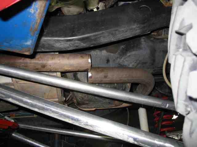
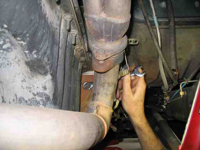
The custom exhaust that was installed to accommodate my Alumi-flex lift was in the way. A Sawsall was put to good use and the exhaust pipe was cut on the passenger side. You will most likely not have to do this on your Jeep. It depends on what mods you may have done prior to your doing the AW-4 swap. The placement of the catalytic converter and the muffler size all come in to play when doing a major modification such as this.
If I was doing this project in the driveway, I would next remove the transfer case from the transmission. This makes the tranny quite a bit lighter and easier to manage. There are six studs that hold the transfer case to the transmission. Remove the nuts and the slide the transfer case off of the transmission’s output shaft. Don’t forget to disconnect the t-case shifter linkage and the electrical connectors for the speedometer sensor and 4WD switch.
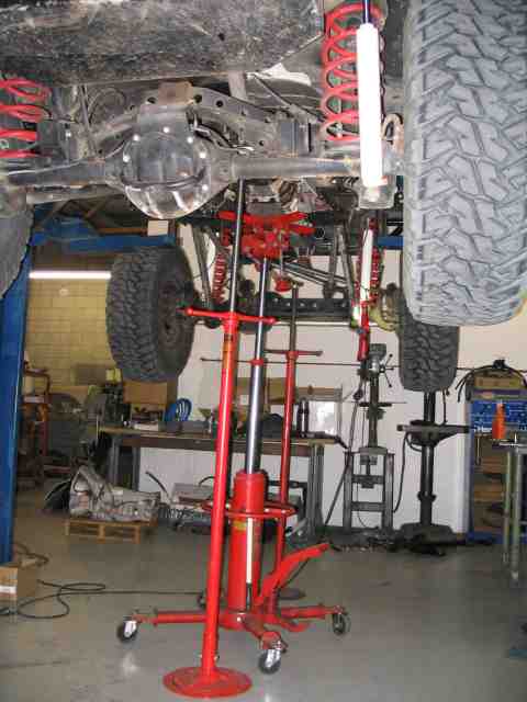
After we were satisfied that all of the wiring harnesses and electrical connectors were removed, we grabbed the transmission jack and moved it into position to take the weight under the middle of the transmission. The bolts attaching the bell housing to the engine block were then removed. Note that there are two E12 bolts at the 11 and 1 o’clock positions. We lowered the tranny jack a bit so as to make the top of the tranny more accessible. The E12 bolts are also called star bolts. If you know what a Torx bolt looks like, this is a reverse Torx (or external Torx).
The screw jack that we had used at the output shaft of the t-case was now moved under the oil pan where we inserted a small block of wood to distribute the weight. By adjusting the height of the screw jack and the tranny jack, we were able to relieve the binding between the engine and transmission and separate the two from each other. It took some wiggling, pulling, and a little help from a small pry bar but all came apart just fine.
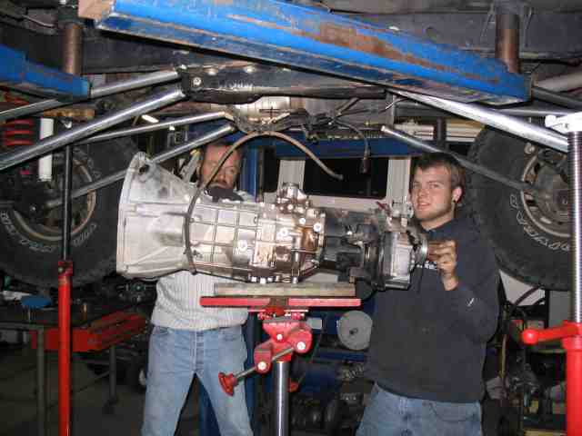
Just to make sure the rather heavy tranny/t-case load didn’t get out of hand, I gave a shout to Jessie and he came over and gave us a hand (Bob on the left, Jessie on the right). Hey, someone had to take the pictures, right? Thanks Jessie for helping get it safely to the floor.
AW-4 Transmission Swap
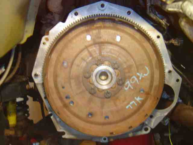
With the tranny removed, Bob and I turned our attention to the clutch. Six bolts attach the clutch to the flywheel. We grabbed a half inch impact wrench and quickly made short work of it. Watch that last bolt when you take it out to keep the flywheel from crunching your toes.
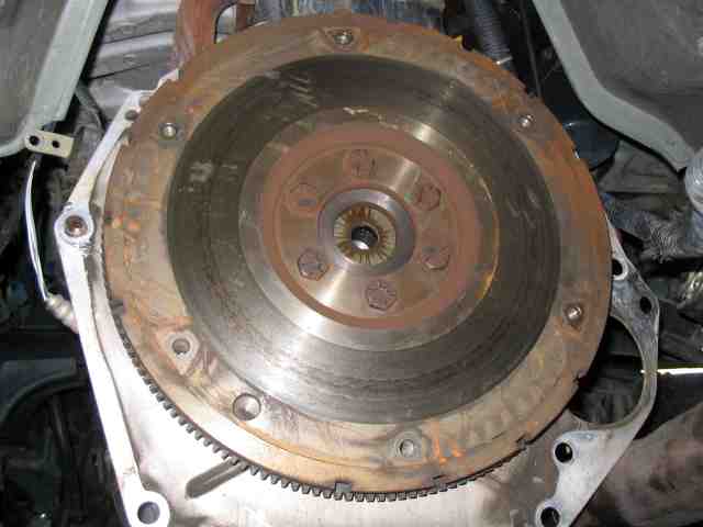
The clutch was set aside and that left the flywheel. It is held in place with a half dozen bolts. The impact wrench was used to remove the bolts. Again, be careful when the last bolt is coming out.
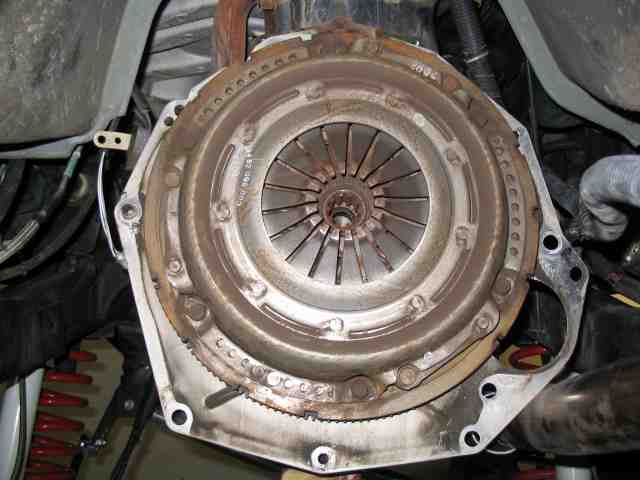
I was quite pleased to see the condition of the clutch and flywheel. There was no discoloration from “smoking the clutch” and no grooves or other marks. There was a reasonable amount of clutch material still remaining before the rivets got into the flywheel. It had approximately 72,500 miles on it. 4.56 gears and a 4:1 transfer case sure makes for a longer clutch life. I’ve been on the trail and smelled the hot clutch from other Jeeps. Too bad for them.
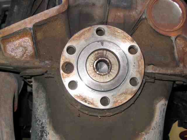
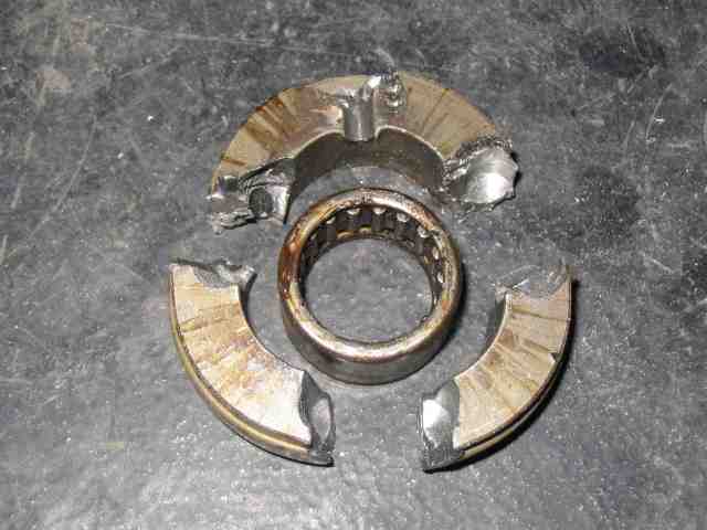
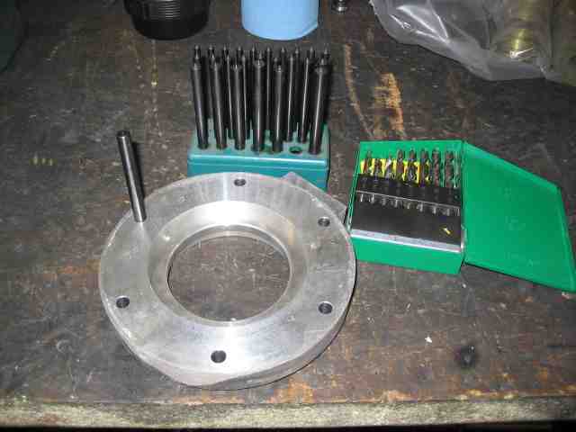
The business end of the crankshaft was next on the list of “things to do” before the AW-4 could be installed. The pilot bushing and the spacer around it had to be removed. Neither were needed by the torque converter which was going to be parked in the end of the crankshaft.
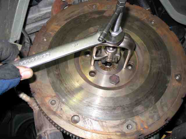
While NOT at all necessary to “save” the pilot bearing, I decided to give this nifty bearing puller a try. Troy had it in one of his tool box drawers and so I decided to give it a shot. I had to put the flywheel back on so that the puller could function as intended (there was a ridge without the flywheel installed that caused the puller to sit off-camber).
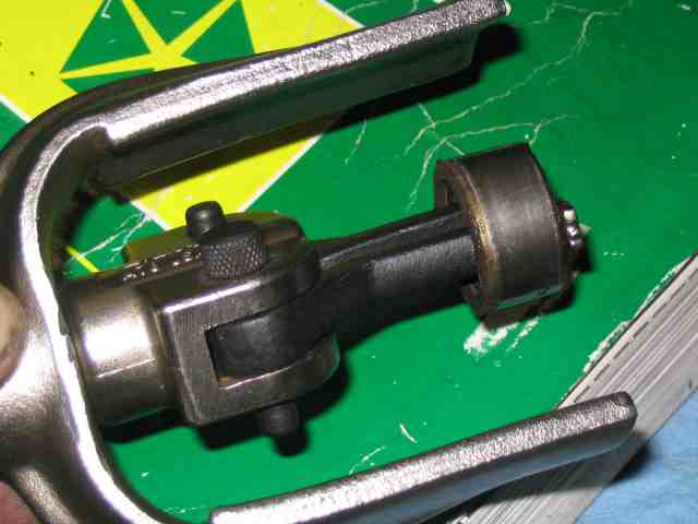
And there you have it. The perfectly good pilot bearing very cleanly extracted by the puller….still in good shape (although it will end up in the trash as I’ve no need for it). It is always nice to have the right tool for the job as it honestly does make it easier.
AW-4 Transmission Swap
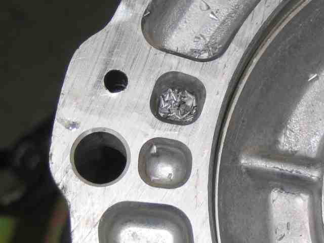
Following the procedure that ScottK described in his write-up, I drill a couple of holes (three of them in fact) in the spacer that surrounded the pilot bushing. Be careful when you drill as you don’t want to hit the crankshaft (sides or bottom). If you do, you’ll need to clean it up before you try to fit the torque converter into the end of the crankshaft. Here is what is left of the spacer after holes and a good sharp chisel assault. Use a sharp chisel….yes, it is worth the time it takes to put a good edge on it.
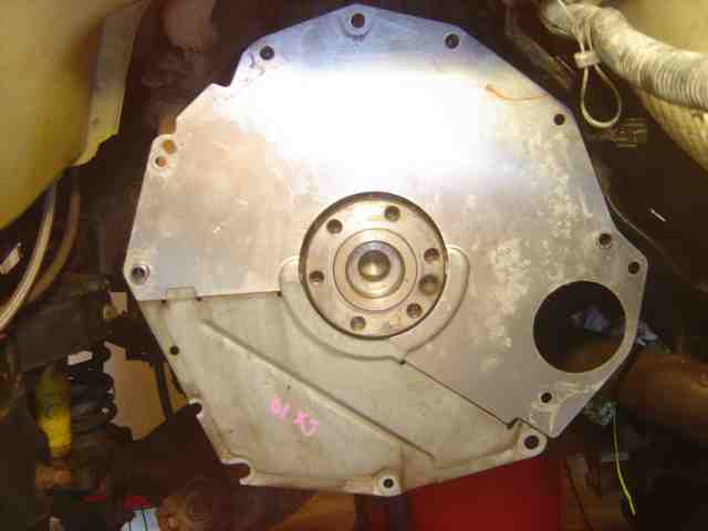
With the end of the crankshaft cleaned up and ready to go, the two piece dust shield is installed. It slips over a couple of guide pins. Make sure you get it lined up….no need to force it.
With that taken care of, the flex plate was the next item to be installed as we were pretty much done taking stuff off of the TJ. I apologize for not getting a picture of the flex plate (and dust shield). They were supplied by Scott00TJ which he took while doing his install. I tell you, when you get on a roll wrenchin’, it is difficult to remember to stop and snap pics of everything done, especially when you have a power house buddy like Bob who is ripping to get stuff done!
The upper section of dust shield is placed onto the back of the engine. Slip it over the two guide pins that protrude from the engine block (about 3 and 9 o’clock). It only fits one way and and you should note that when properly positioned, it fits in a slot that goes around the rear main seal housing. The cutout area for the starter is quite obvious. If you fail in properly positioning the dust shield, pack up all your junk and go pay someone to finish the swap for you. (just kidding)
With the dust shield in place, place the flex plate over the end of the crank shaft. There are six holes and you will quickly find that there is only ONE position where all six holes align correctly. This is so that the timing slots at the edge of the flex plate will align correctly with the piston firing order and the CPS/PCM will be able to detect what cylinder is ready to get spark in the proper order.
With the flex plate in position, place the space over the end of the crank shaft and position it so that the six holes are aligned correctly, just like you did with the flex plate.
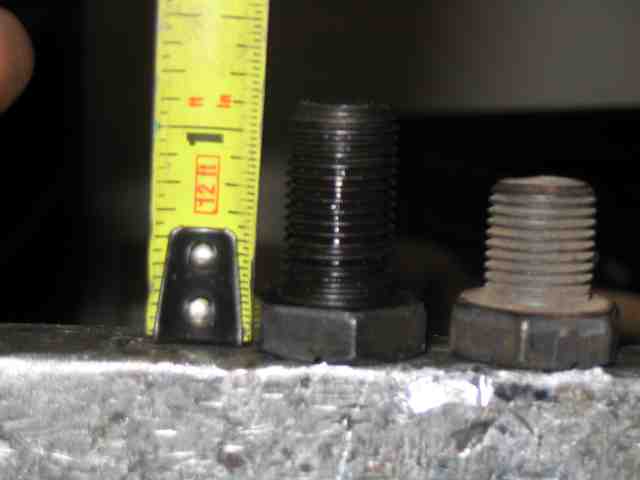
In case you were wondering, yes, the length of the bolts holding the flywheel onto the end of the crankshaft (bolt on the left) is longer than the bolt intended to hold the flex plate onto the end of the crankshaft. As me how I know? Because I forgot. I never really noticed that the 6 bolts I had gotten with the AW4 were in fact shorter until we managed to bottom out the flywheel bolts while attaching the flex plate….DOH! So regardless of what you may have been told, size does matter.
The flex plate mounting bolts were torqued to 55 ft. lbs. I also applied a couple drops of red thread sealant when installing them.
The time had come for Bob to “put the tranny home”…..or something like that. I’m not sure just what he said as he was so excited to get this thing installed. We placed the tranny on the jack and raised it up into position. With some grease on the guide pins and a bit on the front of the torque converter (where it engages the crankshaft), we started to jockey the transmission into position. Be sure your torque converter stays seated during the “get it into position” process.
We closed the gap between the engine block and the front of the tranny a little bit at a time. The jack was raised, lowered, tilted, etc. to help get the tranny into alignment. Likewise, we found it a BIG plus to be able to raise the engine up and down a bit….actually, more of a tilt affect. We had a screw jack under the oil pan (as seen in the previous photo) and this helped quite a bit.
We finally got things lined up and one of the guide pins engaged the hole on the tranny housing. I slipped a bolt in place and engaged a few threads, just enough to hold it in position. Bob then worked the back of the tranny around to get the other guide pin to engage….a little more jockeying with the tranny jack and the screw jack and the 2nd guide pin was starting into the hole in the tranny housing.
NOTE: Do NOT force the tranny up against the engine block by cranking the bolts down. If you have everything aligned correctly, INCLUDING THE TORQUE CONVERTER, you will be able to push the tranny all the way onto the guide pins. If you can’t, something isn’t right. Stop, take a break, and look over your situation and try it again. Forcing the tranny up to the engine block using bolt tightening force will more than likely damage the tranny and/or torque converter (since it has probably become unseated during the process).
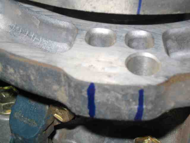
We thought we had a “goof proof” method by which to help get the mounting tabs lined up with the 4 holes in the flex plate. I took a permanent marker and drew a line from the center of the mounting tab (all four of them) to the outer edge of the torque converter. The idea was that we would be able to see the line through the bottom of the dust shield (not yet installed) and then be able to rotate the flex plate to line up the hole. That was a great idea in theory but when we put it to the test, the outer edge of the torque converter (with the marks now on it) could NOT be seen when the tranny was up snug against the engine block. BUMMERS!
AW-4 Transmission Swap
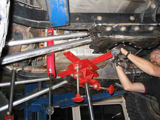
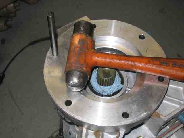
So, Bob thought of another method that did work. I stood at the front of the engine and using my Herculine strength, I turned the pulley on the front of the crank shaft until one of the four mounting holes in the flex plate rolled into position (as you can see in the above photo). By the way, the above photo was taken at the front of the vehicle, looking towards the rear, along the driver’s side of the oil pan. With the mounting hole now in position, Bob was able to sneak a couple of fingers into the dust shield opening and rotate the torque converter. It was easy to see the converter’s mounting tab line up in the flex plate mounting hole. When it was lined up, Bob slipped a torque converter mounting bolt through the flex plate and into the mounting tab of the torque converter. BINGO! Once the first bolt was in place, it was easy to get the remaining three inserted.
After that, I only had to continue to rotate that crank shaft pulley while Bob put the bolts in place. How come the little guy always gets the tough jobs?
When all of the bolts were in place, we made one more go around (that pulley was getting harder to turn) and tightened the bolts to 23 foot pounds.
The tranny was now installed and it was time to slip the transfer case onto the end of the AW-4. HOUSTON, WE HAVE A PROBLEM!
ScottK made the comment in his write-up, in regards to the NP-231’s input shaft length, that a t-case setup with a Tera 4:1 already had the short input shaft and as such, would not have to worry about changing it. I am here to tell you that is wrong. While the Tera 4:1 input shaft is in fact 3/8″ shorter than a regular t-case being pulled off of an AX-15, it will still bottom out in the AW-4 and NOT allow the tranny and t-case mounting flanges a flush fit. It is right at 1/4″ too long.
I was faced with a couple of possible solutions, although none had been explored, to the best of my knowledge, by someone with a Tera 4:1 t-case under these circumstances.
ScottK solved his “too long input shaft” problem by simply buying a short shaft and installing it in his stock t-case.
Since the input shaft is part of the planetary gear set, and I had a 4:1 planetary gear set, I am not at all certain I could even find someone with a short input shaft. At the very least, I would have to open up my t-case and see just what I was dealing with in regards to the planetary. I called Tera a couple of weeks prior to the tranny swap to get their input on what I may or may not experience. They were kind of “you mean you are going to put a Cherokee tranny in a TJ?” and so no help was obtained.
Bob and I scrounged an old 231 from Troy’s discard pile and verified that the input shaft did in fact have to come out of the planetary gear set in order to be worked on. Since I was under a self imposed time schedule for this swap, I didn’t want to spend yet more time playing around with the t-case inner workings and even then, I would have to find a machine shop that could do the work once I had the input gear removed from the case. I checked with Troy and he was not setup to do lathe work on hardened steel. (yeah, we checked the junker input shaft and it was hardened)
Troy suggested I take a cut off wheel and slice the end of the shaft off. Sure, easy to say….but how well would it work when tried? OK….it was either that or drop a couple of grand on a new Atlas II t-case (Troy even had a short shaft sitting there for it. That just isn’t fair!)
I grabbed a ratchet strap from the back of the TJ and strapped the t-case down to a metal work table (kind of reminded me of a metal operating table…..just not as clean).
A length of masking tape was used to mask a line along the input shaft, 3/8″ from the end of the shaft. (Since the input shaft bottomed out with a 1/4″ gap remaining between the tranny and t-case, I decided to add the extra 1/8″ just to make sure there was no pressure on the AW-4 seal.) I used a blue marker to lay a light blue edge on the tape….the idea being that if the blue started to disappear, I was getting off of the designated line. Finally, I took a paper shop towel, folded it several times, and taped it in place….making a large “dust cover” for the seal that was about an inch away from where I was going to be working.
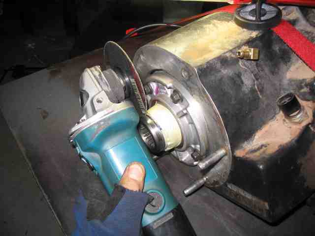
A cutoff wheel was put on a right angle grinder. Bob and I donned hearing protection and safety glasses. Bob did the honors of steadily rotating the output shaft (with the t-case shifted into 2HI) while I ran the cutoff wheel. If things got screwed up, it was pretty much my fault since turning the shaft wasn’t going to make or break this part of the procedure.
I ran the cutoff wheel for about 30~45 seconds at a time while Bob rotated the shaft for me. Steady pressure, cutoff wheel perpendicular to the shaft, don’t get it too hot as you don’t want to heat stress the shaft material or melt the seal that was less than an inch away….NO PROBLEM! And if I screwed this up, what was I going to do? Easiest part of the project thus far!
But in all seriousness, it worked GREAT! It took us about 20 minutes to cut the shaft. 30~45 seconds of cutting and then a short cool down period (maybe 3 minutes). The heat was drawn out of the shaft pretty quickly (faster than what I anticipated). The other end of the input shaft has that BIG gear on it sitting in an ATF bath.
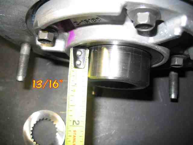
The final dimension for the t-case input shaft was 13/16″, as measured in the above photo. You can see the piece that was cut off laying on the operating table. As you can also see in the photo, I put a slight bevel on the edge of the shaft, similar to what was previously there. The same right angle grinder with a flapper disk in it worked very well for this. I held the grinder in one position while Bob rotated the shaft. I wanted the edge dressed off to help avoid nicking the AW-4 seal when the shaft was slipped into the tranny
I cleaned up the shaft, removing the tape, shop towel, and metal filings (not really too many of those as they were flying all over the place in a shower of sparks). A thin film of grease was applied to the inner and outer surfaces of the shaft. Time to see the fruits of our labor.
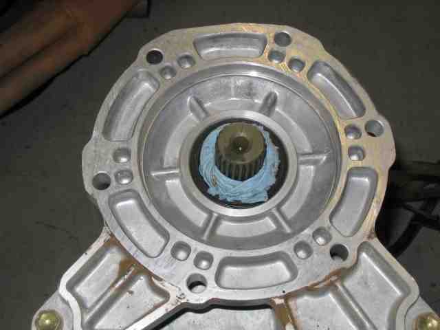
Bob and I walked the t-case over to the tranny and slipped it into position. It fit like a glove….and a perfectly sized glove at that!
I think it is safe to say that more time was spent trying to figure out what to do with the input shaft than it did to actually do it. Thanks to Greg and Troy for suggesting the cutoff wheel idea. Troy was confident that Bob and I could make it work. And once we made the first cut, I felt pretty good about it myself.
The benefits to doing it this way….I didn’t have to spend $125 like ScottK…..there was NO delay time waiting for a machine shop to do the work….and if it didn’t work, I would have thought of something to blame on Bob! (sounds like a win-win situation for me)
AW-4 Transmission Swap
With the t-case’s input shaft at the correct length, the t-case was bolted to the end of the AW4 and that item on my checklist was marked as finished. Now it was time to turn my attention to a tranny mount.
I followed ScottK’s lead on doing this, although I am going to be changing the mount/bracket to one that sits a bit lower. Jumping ahead just a bit (about two days), I found that I have just the slightest CV joint bind when my rear axle is at full droop. My drive shaft length seems to be OK but the CV joint issue must be addressed. Troy took a look and agreed that either the joint needs to be disassembled and a die grinder used to remove the offending metal….OR….redesign the mount to allow the tranny/t-case to fit closer to the skid. The latter idea is the better of the two since it will eliminate the CV bind by reducing the operating angle. At the same time, a reduced operating angle means longer CV joint life expectancy. And lastly, my pinion angle, which is now too low, will not have to be increased nearly as much to align it to the CV drive shaft. A lower pinion angle on the differential means better oiling of the pinion bearing. So all in all, designing a lower mount is the best solution and will be worked on once the vehicle is rolling. (note that I do not have a clearance issue at normal ride height, only when both rear tires are a full droop).
I will note that YOUR setup is probably not like mine. The CV joint on the drive shaft, skid plate height (and brand), and coil spring height all come into play when working through this kind of an issue. Just because I had an issue with it does not mean you will. Just something to consider when you are doing your project planning.
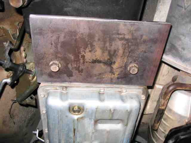
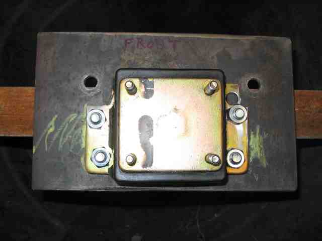
Anyway, back to ScottK’s mounting bracket. I cut a 1/4″ thick plate to a dimension of 6″x10″. Mark a line 2″ from the front edge of the plate. On that line, from the center line of the plate, mark a hole 3 3/8″ towards the driver’s side. Also mark a hole 2 7/8″ towards the passenger side. These two holes are used to mount the plate to the tranny, as shown in the above photo. If memory serves me correctly, I made the holes 1/2″ diameter.
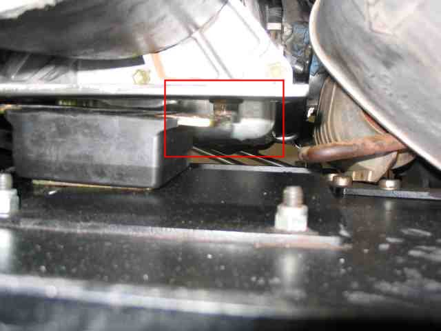
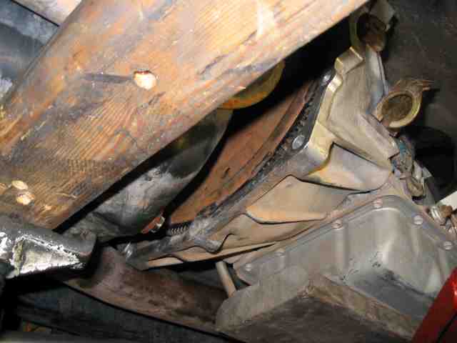
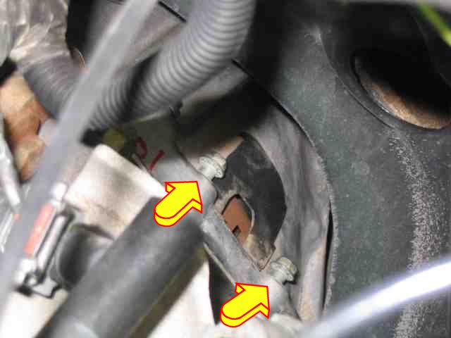
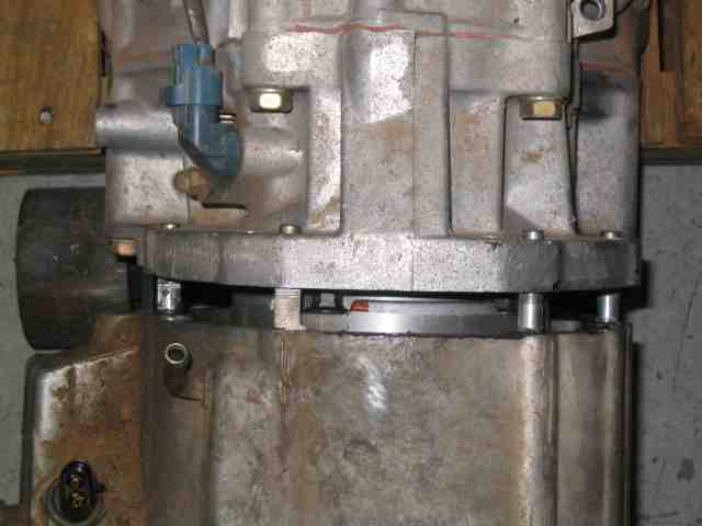
Now it was time to determine the placement of the stock tranny mount on the new plate. To do this, I set the tranny mount on the skid plate (this properly positioned the mount in the existing mounting holes). I then raised the skid plate up into position and put a few bolts in place to hold it. I then slowly lowered the jack holding the tranny until it came to lightly rest on the skid plate. In my case (ScottK also commented on this), a corner of the tranny mount hit the AW4 mounting bolt. The above photo is taken from the rear of the skid plate (look towards the front of the vehicle) and I’ve outlined the area where the AW4 bolt is hitting the stock tranny mount. The other side appeared to clear OK but it too was close.
When I new where the clearance problem was, I lowered the center skid and cut a small part of the tranny mount away.
Once I had the tranny mount trimmed, I put it back in place and raised the center skid one more time to make sure there were no more clearance issues. It looked good so I took a crayon (grease pencil) and traced the outline of the mount against the plate. When I lowered the skid, I could then properly position the mount on the plate and mark the holes needed to bolt those two together.
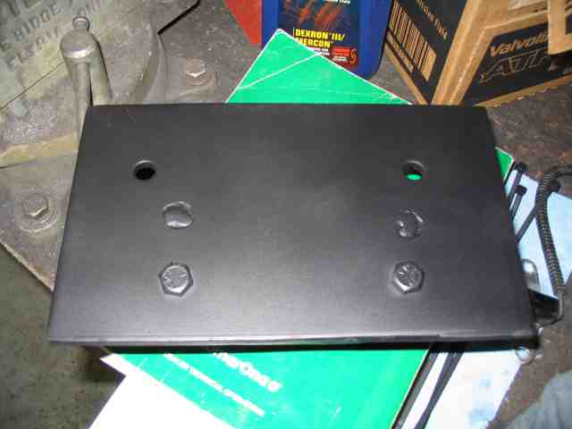
As ScottK mentioned in his write-up, one pair of the tranny mount bolt heads will interfere with the plate bolting flush against the bottom of the AW4. I cut the heads off of a pair of Grade 5 bolts and Troy welded them into the plate for me. The rear most pair of mounting bolts pose no problem so there is no reason to turn them into “mounting studs” like the other pair. The above photo is the flip side of the mounting plate, the side that bolts up flush to the bottom of the AW4.
AW-4 Transmission Swap
It was time to mount the coolers that I ordered from Summit Racing.
Note: As I write this page of the write-up, I can say that I drove the TJ home from Troy’s shop earlier this afternoon. It was about 55 degrees outside (welcome to your typical Arizona December day). I drove about 15 miles in cross town traffic which equates to anything between sitting at a stop light and going 45 MPH. The tranny temp gauge moved between 155 and 165 degrees after I was about half way through the trip. It took the first half of the trip to get it up to 150 degrees. I’ll assume the thermal mass of the transmission itself took a while to warm up. I was on the throttle a bit during the last mile and as I turned down the street to my house, I heard the 12V fan on the second cooler kick on. It was not overly noisy but I did here it. I pulled into the driveway and slipped the tranny into Park. As I sat there, the fan cycled on for about 10~15 second and then would turn over for a minute or so. This repeated itself for several minutes. I put my hand under the fan to ensure it was sucking the air through the cooler and it was (meaning I had the polarity correct for the motor). I was quite impressed with the volume of air it was blowing out of the cooler. Likewise, I was very happy to see it cycling on and off. This cooling setup is subject to change (do I have to say without notice?). Summer is 6 months away and as configured, it may no provide enough cooling. If something gets changed, it will most likely be the pre-cooler (without the fan) and it may end up getting moved so as to catch more air.
OK…back to the installation.
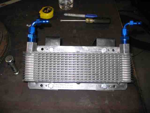
Here is the pre-cooler as intended to go into the vehicle. When I checked for space, I had ample room for the cooler but did not anticipate quite the amount of “overhead” required by the 1/2″ NPT adapter and the 90 degree -6 AN fitting. I tried to purchase a pair of 90 degree NPT to -6 AN fitting but the local performance shop did not have any in stock. I took what they had (as seen in the photo above) and hoped for the best.
NOTE: B&M recommends using anti-seize compound on the threads of their coolers. I kind of “missed” that sentence in their cooler documentation and discovered that the threads in the cooler will gall very easily when an aluminum adapter is screwed into it.
Well, I was wrong. I had adequate clearance for one of the fittings but not for the 2nd one, due to a section of the floor in the TJ. Troy didn’t like the fit at all and so we discussed options.
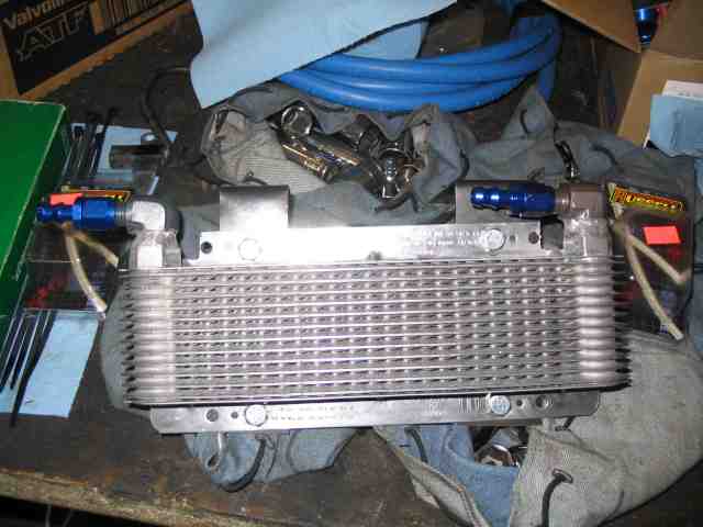
A quick trip down the street to a shop that builds drag racing engines provided the 90 degree fittings I originally had wanted but even those say higher than desired. For what ever reason, B&M’s 1/2″ NPT threads were a little tight and most of the fitting didn’t thread into the cooler all that far. The decision was made to TIG weld the fittings into the cooler after a slight modifiction. I cut 1/2 of the threads off of the cooler and likewise, 1/2 of the 1/2″ NPT threads from the 90 degree fitting. I removed enough of the aluminum threads (used a large sander) to allow the 90 degree fitting to sit down into the cooler’s ports. Troy likes to TIG aluminum and so he took care of that task.
To get an idea of just how much space was saved, take a look at the blue -6 AN fitting in both photos and see where it lines up in relationship to the mounting brackets that are bolted to the cooler. The overall height of the modified configuration is about 2″ less that what I stated with. Needless to say, there was plenty of mounting clearance now.
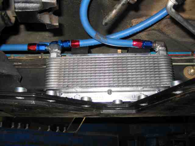
Here is the pre-cooler, tucked up along the frame, driver’s side, about the middle of the center skid plate. I made the L shaped brackets for the cooler and Jessie welded them to the frame. There is an air gap on the back side of the cooler (between it and the frame) of almost 2 inches. I wish the cooler’s orientation was a bit more broadside into the oncoming air flow but there isn’t enough room there to make that happen. In retrospect, I could have made one of the brackets a little shorter and angled the cooler rather than mounting it parallel to the frame. This would have given a more frontal area to the air flow. So….I’ll see how it works out the way I have it. As I mentioned before, this cooler may get moved to a new location in order to increase the efficiency once summer arrives. Since you probably don’t have Phoenix desert temps to content with when July/August rolls around, this may not even be a consideration for you.
I used the Parker hose to connect the inlet of the pre-cooler to the outlet of the AW4. In case you were wondering, the AW4 outlet fluid port is the one furthest forward on the tranny (closest to the engine). The Russell Twist-Lok AN fitting is pushed into the Parker hose. No hose clamp is needed (nor desired) in order to obtain the rated working pressure of 250 PSI.
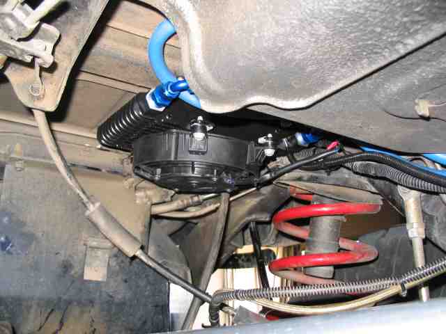
The 12V fan cooler was mounted at the rear of the vehicle, driver’s side, adjacent to the upper spring perch and just forward of the gas tank. I tucked it back into the corner as far as I could get it. I had already check for axle up travel on the previous week’s trail ride and so I knew just how far up the axle would travel. According to my measurements I had about an inch to spare. Let’s hope I was correct. I’ll spend some cautious time on the RTI ramp just to make sure prior to hitting the trail.
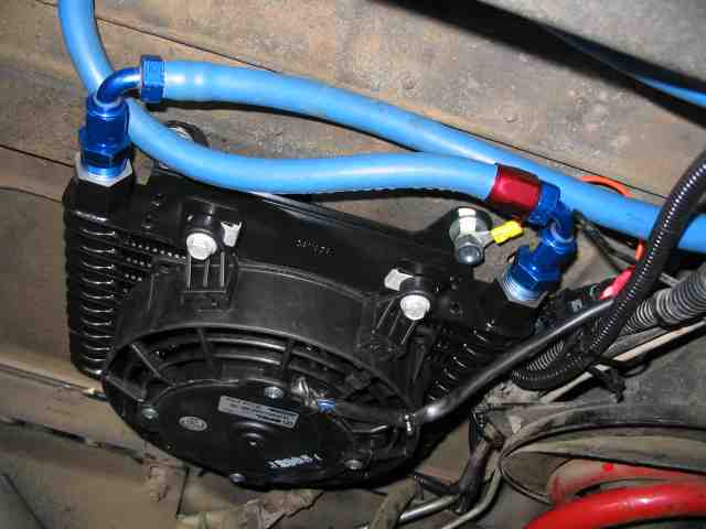
There are four mounting tabs on this cooler and I bolted it through the TJ’s rear floor area. Did I mention that I ended up using the straight AN fittings (that I bought for this cooler) on the pre-cooler? No problem….I had ample hose to allow for the 90 degree AN fittings used here. OK…so where did that red bling cover go on the left hand fitting? I used it on another one that didn’t come with one (different brand of fitting). On the Twist-Lok fittings, the red cover is just that, a cover. It serves no purpose other than to look pretty, which it seems to do when you compare the two fittings in the above photo.
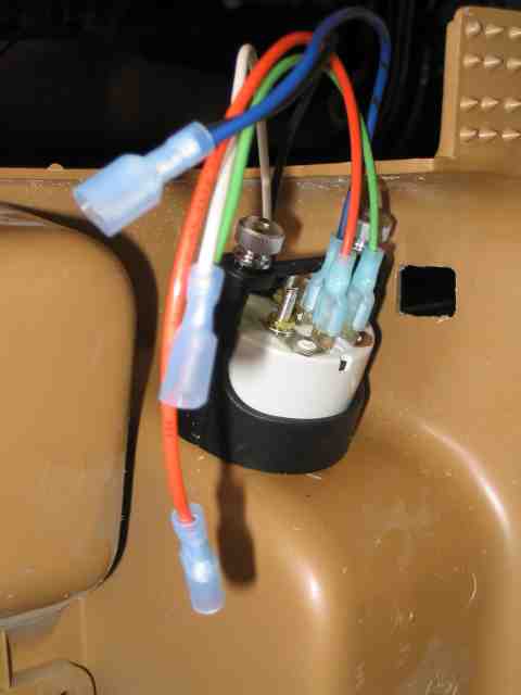
This cooler has a built in thermostat, as I mentioned earlier in the write-up. The documentation that came with the cooler provides a very easy to follow wiring diagram. No power relays are needed and the built in thermostat controls power to the fan once you connect the electrical leads together. Although I have not done it yet (it was not required to get the TJ rolling down the highway), it is my intensions to wire in a 12V LED indicator adjacent to the AW4 temp gauge so that I know when the 12V fan is running. While I can hear it driving down the street in front of my house, I won’t hear it on the freeway. In case you want to wire one, just attach the indicators positive lead to the positive lead of the fan. When the fan turns on (ie., gets +12V from the thermostat), the light will turn on. Then….if the tranny temp gauge does not start dropping here is a problem.
AW-4 Transmission Swap
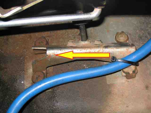
Installing the slightly longer AW4 tranny means the transfer case is shoved rearward the same amount. Doing so gets the transfer case shifting linkage out of sorts with itself. You need to fix it. I opted to keep the same bracket and drill a couple of holes in it. The above photo is of the t-case shifter bracket. It is bolted to the driver’s side of the tranny tunnel, about even with the transmission shifter. I drew the arrow on it because I got it turned around (once removed from the vehicle) and made a set of holes toward the front (DOH!) instead of the rear. So I thought I would emphasize just which way the new holes need to be drilled. This is a “Do as I say, not as I do!” reminder.
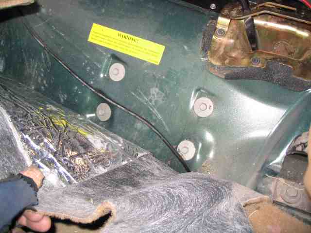
If you pull back the carpeting on the driver’s side of the tranny hump, you will see the 4 mounting bolts for the t-case shifter bracket. Remove them.
Now back to the bracket on the under side of the tranny tunnel. Remove the two bolts that hold the small pivot plate in place. The pivot plate is what the shaft goes through. It is this pivot plate that must be moved.
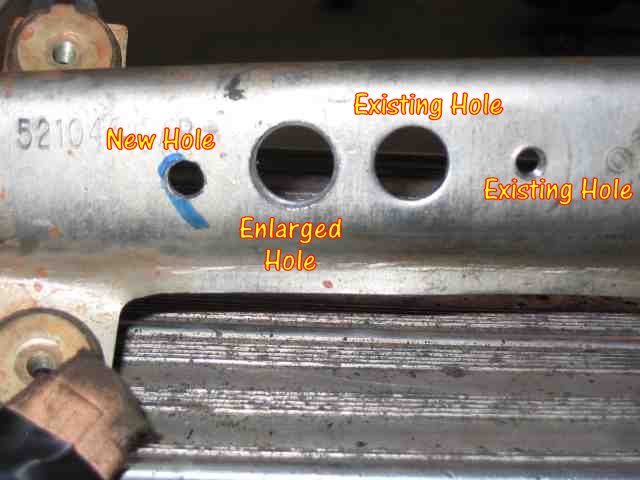
The enlarged hole was one of the tapped holes that previously held the pivot plate. Drill it large enough so that the pivot can move without interference. I did not bother to tap the new hole. If you do, you’ll need an 8mm tap. I just used an 8mm bolt with a nut on the back side. Use a large washer on the back side for the large existing hole.
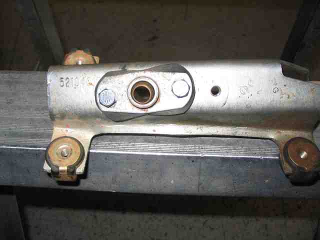
Here is the pivot plate, bolted back into position. NOTE: I drilled the holes at the wrong end of the bracket. Make sure you get yours “relocated” at the other end of the bracket. I hate it when those senior moments come.
When you have the pivot plate back on the bracket, bolt the bracket back onto the side of the tranny tunnel and reassemble your t-case shifting linkage.
AW-4 Transmission Swap
The shifter mounting plate must be removed so that the new mounting plate for the AW4 shifter can be installed. If you look around the edge of the plate, you will see that it is held on with some self tapping screws. Remove the screws and keep them to install the new plate.
When ScottK did his AW4 swap, he got a TJ shifter, shifter mounting plate, and shifter cable from a TJ. When I got my tranny from Nacho, he didn’t have any TJ automatic parts in inventory. He was quite confident that the XJ shifter mounting plate would work as well as the XJ shifter. I left with all the parts in hand except for the shifter mounting plate.
I stopped by the local Jeep dealership and got some assistance from one of the guys working at the parts counter. He was kind enough to look up the part numbers for a ’98 XJ automatic (which was the donor for my shifter parts) and compared them to a ’98 TJ automatic. The shifter mounting plate for both vehicles shared the same part number. However, the actual shifter part number was different. The more I thought about it, the more I decided that the difference was probably cosmetic (maybe one was a little longer than the other) or that it may have something to do with the ignition lock. Nacho is usually pretty accurate on his Jeep parts so I stayed with my XJ shifter and ordered the shifter mounting plate, part # 53000704.
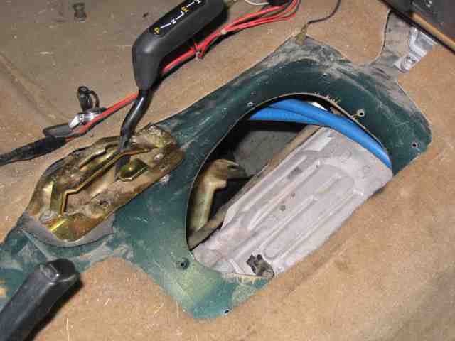
The screws holding down the t-case shifter will have to be loosened too as it overlaps the shifter mounting plate. My mounting plate had some rather dead looking weather stripping on it. I scraped it off the tub so I could get a clean sealing surface for the new plate. (hey, you can see the AW4 tranny through that big hole!)
Here is a picture of the new shifter mounting plate on the tranny tunnel and screwed into position. As I didn’t have any weather stripping on hand, I used some RTV. I believe it worked well, although taking it off may be a bit more difficult than the old weather stripping.
As you can see, the 4 mounting holes on the XJ shifter line up perfectly. Nacho was correct! If memory serves me correctly, I used some short 3/8″ bolts to secure the shifter to the mounting plate. In case you were wondering, the shifter handle can be removed by depressing its button and firmly pulling the knob from the shifter. To install the shifter handle, just push it onto the shifter.
You’ll need someplace for the cable to leave the cab and get down to the AW4. The TJ has a round plug in the firewall that is made for this. Push it out from the inside of the vehicle.
NOTE: I did find that the rubber grommet that comes on the XJ shifter cable is just a bit undersized to properly fill the hole in the TJ’s firewall. So….that is one thing on my “to do” list. I think I’ll take some thin sheet metal and make a plate to properly cover/fill the firewall hole and RTV it into place. The last think I want is that hot engine compartment air blowing into the TJ.
The shifter cable slips into the shifter bracket. There are some locking tabs on the shifter cable that latch into position to secure it to the shifter. The inner cable has a plastic socket that snaps onto a ball on the shifter.
The tranny end of the shifter cable is held in place by the zinc plated bracket in the above photo. The end of the shifter cables snaps into the bracket and the plastic end of the cable is pressed over the ball on the shift linkage. Pretty simple install. Just route the shifter cable out of the fire wall and down to the tranny. It is not a long cable and so you really only have one path to follow, else it won’t reach.
AW-4 Transmission Swap
This page has been added since the initial write-up was made available. I had gotten a letter from MikeJ who was gathering parts for an AW4 swap. He had read ScottK’s write-up and wrote me to ask how the backup lights were wired. ScottK’s write-up didn’t address it and up until this page was added, my write-up didn’t either.
So here is the necessary info to get your lights hooked up.
The XJ, when equipped with an AW4 tranny, powers the backup lights via the +12V that comes from the Transmission Range Sensor (pin 6). (That is the assembly that the 8 pin Gray plug attaches to on the passenger side of the AW4). The same +12V can be obtained at the TCU (pin 18).
If I had given some thought to the backup lights when I still had the AW4 sitting on the floor, I would have soldered about 3 feet of wire to the wire on pin 6 of the Transmission Range Sensor and left it until I got the tranny installed. But I didn’t, so here is what I did post installation.
Looking down at the top of AW4, you will see the wire harness that was plugged into the AX-15. This was connected to the backup light switch on the AX-15. ScottK mentioned in his write-up that you should remove this plug and toss it. I found it easier to modify the plug and continue using it.
Slide the red clip to one side so that you can pull the plug apart and temporarily separate it from the TJ’s harness. If you have room to work on it, you can leave the plug in place if you wish. Remove the tape that the factory folks wrapped around the wires. When you do, you will see that pins 1 and 3 of the 4 conductor plug are connected together. This is the “jumper” wire that, when not removed, bypasses the Park/Neutral Safety Switch on the AW4. If you want to be able to only start your TJ in Park or Neutral, cut both ends of the jumper next to the body of the plug.
I then cut the two conductor AX-15 backup light connector off of the harness, leaving the two wires (coming out of the 4 pin connector) as long as possible. One of these two wires is +12V (Violet/White) and won’t be used. I folded it in half and then slipped a piece of heat shrink tubing over it and sealed it up.
The remaining needs to be connected to the Reverse circuit. I soldered a length of 18 gauge wire to it and connected it to the above mentioned pin 18 at the TCU. When the shifter is placed into Reverse, the transmission range sensor will output +12V to that wire and the backup lights will illuminate.
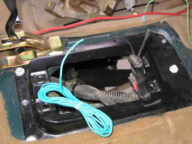
I slipped the wire I soldered onto the Violet/Black wire into some loom material and routed it along the driver’s side of the tranny and then up through the hole in the firewall where I connected it to the TCU.
As I said earlier, had I given this some consideration before the tranny was installed, I would have been dealing with a foot or two of wire connected between the shifter on the side of the tranny and this modified plug.
AW-4 Transmission Swap
The AW4 transmission, like most others, uses a throttle valve (TV) cable. The TV cable helps control shift speed, quality, and part-throttle downshift sensitivity. If the cable is too loose, early shifts may occur. If the cable is too tight, delayed shifts may occur and part-throttle down shifts may be too sensitive.
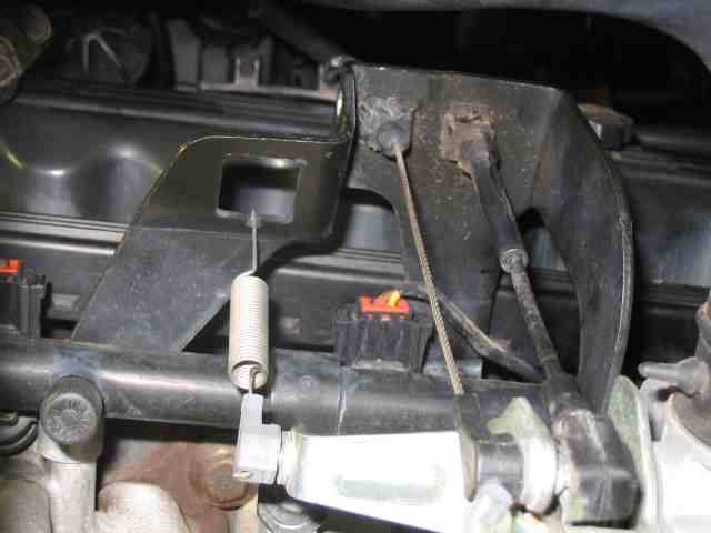
The cable bracket for the throttle body comes setup for the TV cable. The spring shown in the above photo must be removed to make room for the TV cable. Unhook it from the bracket. The other end can be pushed off of the throttle linkage.
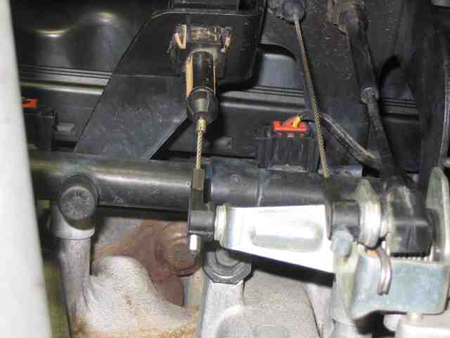
With the spring removed, the end of the TV cable is inserted into the bracket and similar to the shifter cable, locking tabs secure it in place. If you look at the top of the valve cover, you should see some clips where the throttle cable is secured. Mine had an extra slot available for the TV cable. The other end of the TV cable is attached to the AW4 and is not intended to be removed (unlike this end).
There is a spring loaded plunger on the top of the TV cable (where it locks into the bracket near the throttle body). By pushing the plunger (my thumb is on it in the above photo), you can adjust the tension on the TV cable. You want to set the cable tension so that the TV cable is in sync with the throttle body. In other words, just as the throttle body begins to move, any slack in the TV cable is gone and it too begins to move. To put it another way, you don’t want any pre-load nor any slop in the cable.
And since you are under the hood hooking things up, don’t forget to install the CPS (crank shaft position sensor) into the AW4’s housing. It is located slightly to the driver’s side on the top of the AW4 housing. Looking down past the end of the manifold will get you lined up on where it goes. While the stock 3 speed TJ auto tranny’s CPS relied on an air gap for proper operation, you can install the CPS from the manual tranny by simply bolting it into position. I found it easier to get to the mounting bolts by reaching up from the bottom rather than down from the top. Your results may vary.
AW-4 Transmission Swap
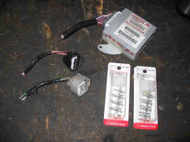
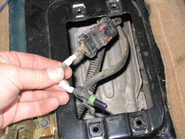
The above photo shows what can sometimes be the toughest parts to find for your project. These were cut from a totaled ’98 XJ that still had its vehicle wiring harness intact. From personal experience, it is apparent that most salvage/junk yards will not cut connectors out of a harness unless the harness was physically damaged in the wreck. A complete vehicle harness commands a good price on the used market. A harness with missing tranny connectors doesn’t. As you can see, I was able to get the matching halves of both the gray and black plugs (as previously mentioned) as well as the 26 pin plug that is needed for the TCU (upper right corner of the photo). The salvage yard owner was a pretty nice guy and reluctantly sold me the gray, black, and TCU plugs for $20. He had one of this yard rats cut the connectors from the harness (I got to supervise!). Since the young kid had quite a time getting the TCU connector out of the vehicle (the driver’s side door was smashed in from the accident and so getting under the driver’s side dash was a major pain), I gave the kid a tip and tossed the owner an extra $10. At that point in time, I was on the start of my second day walking the junk yards looking for a ’98-’01 donor XJ….and so when I finally found one that had the plugs still in it, I was pretty happy. The owner, the yard rat, and myself parted company all better off than when we first met. FYI, I had already checked at the Jeep dealership’s parts counter and those plugs are NOT available without buying the entire harness (you can imagine what that might cost).
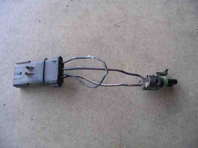
In all honesty, one could implement a work around for the gray and black plugs if they were not available. It would cost you $10 to purchase a pair of 9 pin molex connectors like those shown in the photo. You would then cut the black and gray plugs from the transmission’s wiring harness and attach the new 9 pin connectors. The matching halves of these two connectors would then be spliced into your TJ’s wiring harness in the exact same manner that the gray and black plugs in the above photo will be attached to my TJ. The only drawback to this is that IF you ever swapped in another AW-4 to replace the one you have, you would have to spend 30 minutes to convert its gray and black plugs over to the 9 pin connectors that you were using. By the way, those 9 pin connectors can be had from your local Radio Shack store. (I’ll explain their intended use later in the project.)
It is mandatory that you obtain the 26 pin TCU connector. Doing a work around for that is next to impossible. There is nothing at the local Radio Shack that could be substituted for the real thing (unlike the gray and black plugs). I would not even consider soldering the individual harness wires to the TCU’s connector pins. No way! You need the tranny computer connector, period, end of discussion.
While there will be more about the TCU’s wiring harness later in the project, I’ll provide a little bit of info here so you can get an idea of what is involved. If you have acquired the AW-4 as I did, with its black and gray plugs intact, and you have the matching halves of those two plugs along with the TCU connector, what you will be doing is making a wiring harness that attaches those plugs together (and to your TJ). To do this, one first needs a spool of 18 gauge stranded copper wire. Skip the trip to Radio Shack for the wire as they usually sell it in 25′ rolls and the pricing is too high for the amount you will need. Try a good automotive parts store or a well stocked electrical supply store. I recently came across a company called Del City and they have a great selection of automotive related electrical components and their prices are competitive.
You will also need a good soldering iron or gun, rosin core solder (do NOT use acid core solder!), and several feet of heat shrink tubing. The simple description of the task is that you will solder pre-cut lengths of wire onto the pigtails of the connectors. Each soldered connection is then covered with a piece of heat shrink tubing. The other end of the wire is connected to one of the other plugs. When you are done, you’ll have a harness with a 26 pin TCU plug on one end with a gray and black plug on the other end. There will also be a handful of wires that will be connected to your TJ’s harness (more on that later). It is not technically difficult since the wiring diagrams are provided for you in this write-up. If you can not solder neatly, solicit the help from a friend that does neat work. It doesn’t have to be NASA space shuttle quality, but it does have to be done correctly so that you won’t have electrical problems on the trail.
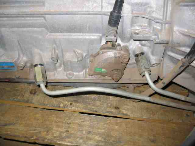
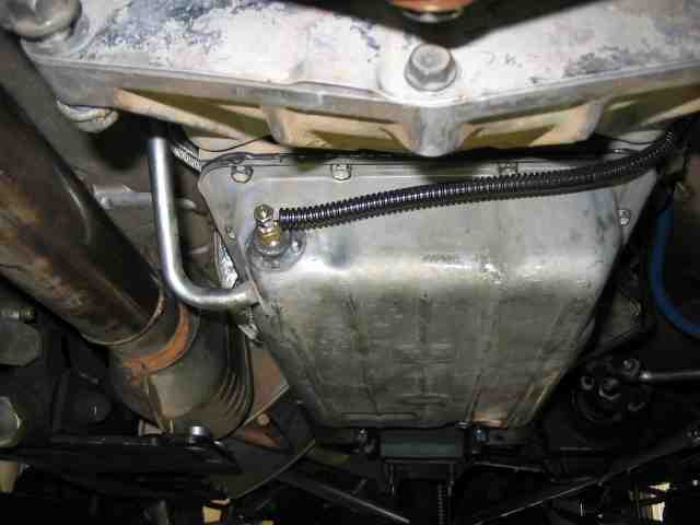
OK, back to the transmission. Here is a photo of the passenger side where the two cooling lines connect to the tranny. The XJ had aluminum hard line cooling lines that were routed up to the radiator. I’ve decided not to use the TJ’s radiator for tranny cooling for a couple of reasons. First, I do not wish to run my tranny fluid through a 210F radiator in hopes of keeping it cool. In my opinion, that is warmer than the fluid needs to be. I hope to keep it in the 150F~190F range most of the time. Secondly, with the winch parked up front, the TJ has a fairly maxed out cooling system when cruising down the freeway in mid-August in central Arizona. Adding tranny heat to the existing cooling load will simply add to a potential problem.
Update: OK…so it has been a few years since I’ve installed the AW4 in my TJ. Based on the info/experience I had at the time, I opted to not use the TJ’s radiator to cool the tranny fluid. Knowing what I know now and the experience I’ve had with my AW-4 swap, I would route the tranny fluid through the vehicle’s radiator and then to the same 12V aux cooler that I currently use. I omit the use of the stacked plate cooler in front of the radiator that is shown in this write-up. The reasons for this….the ATF doesn’t warm up well in the winter months (and our winters here in Phoenix would be MUCH warmer than most any other place in the country). I would also I’ll get better fluid coolring for highway and city traffic in the summer. It is not an issue on the trails, but more so as one drives around time. I believe the 4 LO on the trail makes the torque converter’s job fairly easy.
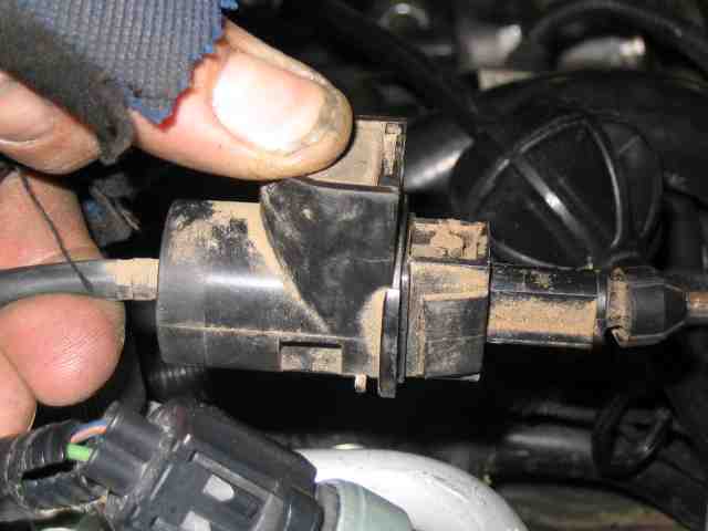
Since I am not using the tranny’s hard cooling line, the quick disconnect fittings in the above photo need to be replaced with something that will meet my needs.
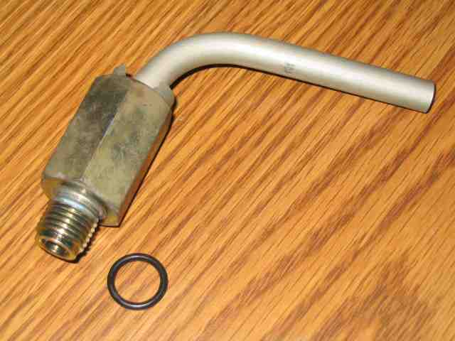
I cut the aluminum line with a tubing cutter and took the fitting with me for a quick trip to the local speed/performance shop. Note that this place is NOT a 4×4 store….it is stacked with gear heads that do car things, not Jeep things. But they have a big wall full of hose ends and adapters….and that is what I needed for this part of the project. The o-ring was seated at the end of the threads against the body of the fitting. (hold on to it, you may need it)
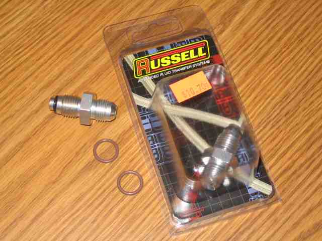
A pair of Russell adapters were purchased at the local performance shop. The Russell adapter part # is 648070. It is a -6 to 14mm x 1.5 fitting and was just under $11 each. These thread directly into the AW-4 fluid ports where the quick disconnect fittings were removed. The counter guy at the speed shop tossed in the tan -6 o-rings (not included with the new fitting) since I spent $200 in the store before I walked out. He mentioned that these adapters are commonly used for power steering boxes. With these adapters installed, I have a -6 AN connection that allows me to connect the -6 (3/8″) fluid cooling hose to the transmission. If the o-rings on the factory quick disconnect fittings appear to be in good shape, they can be used on the AN adapter.
AW-4 Transmission Swap
I drilled a hole into the front of the tranny pan and Troy welded a bung into it. The Auto-Meter tranny temp sensor, which happens to be 1/8″ NPT, is then screwed into the bung. The interior clearance is good in this corner. Given the depth of the sensor, this is about the only spot in the pan where it can be mounted. Other choices for monitoring tranny temp include installation of a temp sensor in either of the two ATF fluid lines. When this is done, the exit line (hottest fluid) is normally used.
The Auto-Meter temp gauge requires a 2 1/16″ hole for proper mounting. I removed the power switch that was used for my rock lights and donated the space to the temp gauge. I figured that finding another spot to mount a power switch was going to be easier than finding a different spot for the gauge. I used my Dremel tool to cut the hole in the console.
I set the gauge up with pigtail connections, about 6″ long, so I could more easily disconnect the wiring from the gauge should I need to remove the console in the future. It beats getting ones fingers up behind the plastic to disconnect the wires.
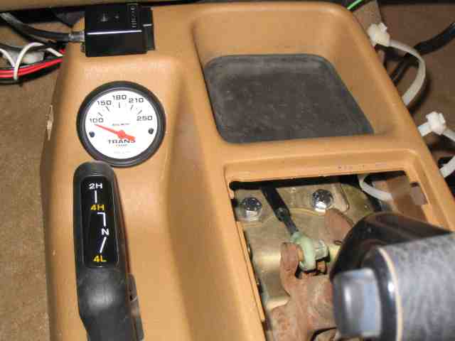
A photo of the gauge installed in the center console. Auto-Meter supplies a light assembly for the gauge. You get your choice of red or green illumination. I chose red….looks pretty good at night.
For gauge power, you need to tie into an ignition switched circuit. In other words, the circuit goes live when you turn the ignition key to the on position. I opted to use the switched 12V circuit that is available behind the glove box on the early model TJs. I didn’t feel like running a separate wire for dimming the gauge light so I tied it to the 12V switch circuit as well.
AW-4 Transmission Swap
This page contains those odds and ends comments, photos, and miscellaneous changes for the project. In other words, I either forgot to include something in an earlier page (20 of them as I write this) or something came along that caused me to change the way I had previously set up something. So, it gets added here so you get to see it.
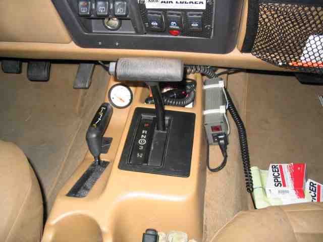
I realized that I didn’t have a picture of the center console with the shift indicator installed. So this is what it looks like when it is all back together.
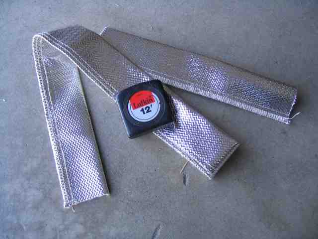
I believe I mentioned that my long arm lift makes for a cramped exhaust system along the passenger side of the center skid. A trip to the local performance shop (same place I got the Parker hose, -AN fittings, etc.) provided the same heat shield covering that Troy had used on a recent V-8 swap. It comes in a variety of sizes to slide over regular hose. I picked up the -10 size since I had to get it over the already installed fittings (one would normally slide this onto the hose prior to attaching the fittings) and around a 90 degree fitting. This heat shield is being used on the fluid hoses for the AW4. They are close to the exhaust system and the IR heat gun shows that the material does a pretty good job in reflecting away the heat. The real test will be during the summer when rock crawling. Price is about $4 per foot (varies with the size of the covering).
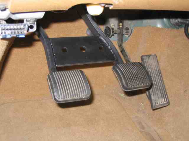
I had a little time today and so I took care of the brake pedal. ScottK used a stock auto tranny brake pedal on his and it sure made it look factory. I opted to weld my clutch and brake pedals together. A good friend said he runs his this way and found it to work better than the factory auto brake pedal. It was easy to shape the bracket and since I put racing holes in it, I know my TJ will go faster just because of that. Troy was kind enough to tig it in place for me. (Did I mention that I suck at welding?) If you go this route, don’t forget to remove the rubber pads prior to welding….else you will have a gooey mess on your hands by the time you are done.
That is about it for this write-up. I hope you have found it helpful. I tried to cover a number of different issues that I ran across and some of the more common ones that most folks usually ask about.
Comments from 1/7/2006:
I sooooooo enjoyed trying out my TJ on the trail today. It was everything I was hoping for and just a bit more.
It was the first shakedown run for me since installing the AW4. While I have rolled several hundred city/highway miles since the install, this was the first day when the t-case was put into 4HI and 4LO and the lockers were fired up.
We ran an easy wash for the first part of the outing. I wanted to make sure my front locker was behaving correctly after having repaired it, installing new axles, and setting up the gears.
The next trail started out with a water fall that is done in two stages. I played on the lower section with the new tranny….basically getting the feel for it with the weight transferred to the rear axle. The top half of the water fall found me on a line that I’d avoided before….hey, the bottom half was a blast so why not push it a little more. I managed 3 tires on the rock and carried one several feet in the air….felt very comfortable doing so. My buddy got nervous and was volunteering for ballast duty, but I declined….gotta learn where the edge of the envelope is, right? I crested the top and gently laid the carried tire back down onto the rock. Mission accomplished.
Some observations from my first trip out:
#1. I DO NOT regret leaving the 4:1 t-case in the TJ. My buddy has the 3 spd TJ auto in his and he rode the brakes dropping down into the washes while I let the engine braking take care of it for me. I was totally impressed with just how steep a descent one can make with my setup when the engine is holding at 1250 RPM on the steep down-hills. I would not have been happy with stock low range gears.
#2. Not as much heat is generated by the torque converter when those 4:1 gears are doing their job. When I was playing on the water fall, the cooling fan cycled on and off and the temp maxed out at 180F. (mind you, there is no tranny cooler catching air from the radiator fan) When I was just crawling through the wash (no waterfalls), the temp was usually about 150~165F. When the fan did kick on, it only ran for about 20 seconds. The freeway ride, home, with about 80F ambient air temp, had the tranny temp sitting just under 150F.
#3. I had more than enough brake performance to stop myself when in LO range. The 1 ton hydroboost did an outstanding job and I am confident that having it made the trail all that more enjoyable. There is absolutely no feeling of overdriving your brakes.
#4. I didn’t drive nearly as much with both feet as I expected I might. Where I was expecting the 4:1 gears to pretty much make forward progress a continuous thing, I found that a medium size rock in front of the front tire left the torque converter just sitting there, waiting for me to give it more gas.
#5. I miss my hand throttle. I felt somewhat lost without it and found myself on numerous occasions searching for it with my finger. Yes, I know it is not nearly as important as it was before, but all those trails with such a good friend will take me a while to adapt to its absence.
Comments from 4/9/2006:
With the tranny pan extending forward of the t-case skid, I needed something in place to protect it from rocks and other things likely to punch a hole in it.
I finished my new aluminum engine & tranny pan skid this weekend. It turned out quite well, in my opinion. Hopefully it will give you some ideas if you decide to make your own skid.
I believe I mentioned that the grommet on the XJ shifter cable was undersized for the hole in my TJ’s firewall. For he past 3 months, it really hasn’t been much of an issue….up until spring finally arrived that is. Now, with day time temps hitting in the low 80s, I can feel the heat from the engine compartment flowing around the grommet. It makes for a warm right ankle.
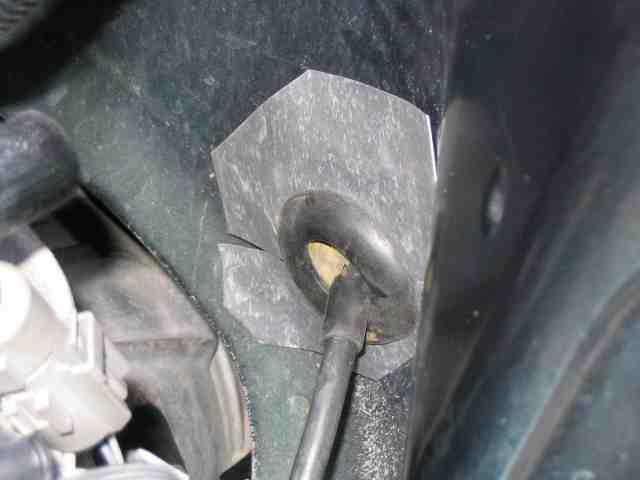
Using some thin aluminum flashing, the kind you can get at the local hardware store for roofing work, I cut a hole in it to fit around the rubber grommet. A slit cut to the center allows one to slip it over the cable. From there, I worked the edge of the grommet through the hole until I had it all the way through as shown in the above photo.
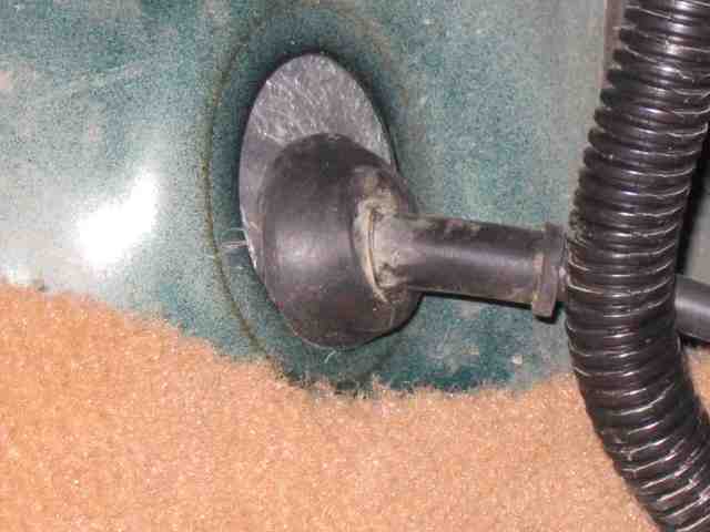
A view of the firewall hole from the inside of the vehicle. As you can see, the grommet is undersized. The aluminum flashing seals the hole very nicely.
To keep everything in place and to make things a bit more waterproof, I applied a generous amount of RTV to the flashing (on both sides of the firewall) to help seal everything.
Enjoy and remember to TREADLightly!
AW-4 Transmission Swap
Since the radiator was out of the running for transmission fluid cooling, I had to come up with something else. Auxiliary coolers are often added to vehicles when they see trailer towing or other heavy duty service. These are usually mounted up front in the air stream, just behind the vehicle’s grill. Mounting my cooler there would only add to the heat load of the radiator (sucking hotter air through the radiator won’t make it cool better) so I decided to use two stacked plate fluid coolers to handle the tranny fluid cooling chores.
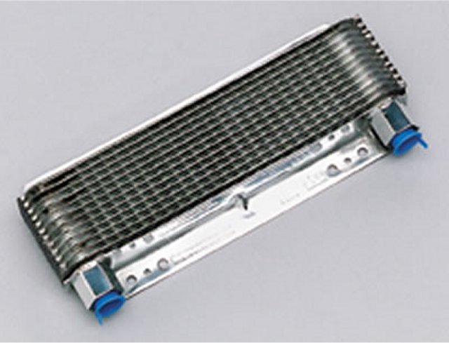
The first stacked plate cooler will act as a pre-cooler. I call it my pre-cooler since the hot transmission fluid will encounter this cooler first upon leaving the AW-4. It is my intention to mount this cooler in such a fashion as to get some air flow across the plates while the TJ is moving. (yeah I know, not exactly a novel idea) What I mean is that I hope this cooler will reduce the fluid temperature enough, during routine city/highway driving, such that the second cooler has less to do. (more on that below) The core size of this unit is 2.5″x11″x1.5″, which is not exceptionally large compared to many. I ordered it from www.summitracing.com , part number BMM-70265. Cost was about $46.
I chose a stacked plate cooler design over the less expensive tube and fin type as they are more suited for off-highway use. Stones and pebbles will have less of a tendency to damage this type of cooler. If you’ve ever mounted/used a tube and fin cooler, you know it takes next to nothing to bend a bunch of the fins and thus reduce the air flow through the unit. While I plan to mount the two coolers in the safest place I can, I still have to remember that the TJ is going to be playing in the rocks and brush. The stacked plate coolers usually have integrated mounting tabs/brackets while tube and fin units end up getting held in place with zip ties and such.
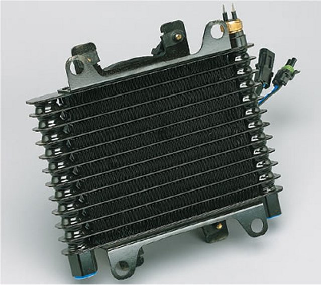
The second cooler is also a stacked plate model but comes equipped with a 12 volt fan. This setup is designed to make its own air flow to cool things down. This particular unit is slightly larger, with the core measuring 8.5″x6.5″x1.5″. The fan is thermostatically controlled and pushes air through the core at about 400 CFM when the fluid temp hits 175F degrees. The fan cuts off at about 160F degrees. Below that temperature, the fan is off. It is my hope, as I mentioned earlier, that the pre-cooler will keep the fluid temperature low enough so that fan use is kept to a minimum, at least while doing city/highway driving. The tranny fluid, upon leaving this cooler, is returned to the transmission. I ordered it from www.summitracing.com , part number BMM-70298. Cost was about $190.
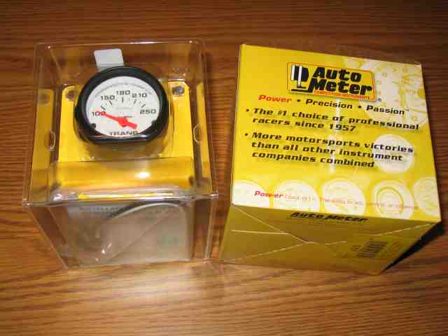
I’m not betting the farm on my two stage fluid cooling configuration without being able to monitor just what is happening. I picked up an Auto Meter transmission temperature gauge to take care of that task. Heat is the worst enemy of an automatic transmission since it will drastically shorten the useful life of the transmission fluid. Once the fluid has been overheated, your tranny suffers badly….it doesn’t take that long before major problems surface. This gauge comes with a remote sending unit that will be mounted in the tranny pan. That will give me a good idea of what the average operating temp is of the fluid. I picked up the gauge at a local performance shop. I saw them listed on the Summit Racing web site for about $45. The AutoMeter part # is 5757.
AW-4 Transmission Swap
T-Day (tranny install day) was sitting at T minus 6 and counting. I had made a checklist of things I needed to do before I put the TJ on the hoist for the actual swap. One by one, I was getting them checked off. I found myself with a bit of spare time so I decided it was time to clock the transfer case. I had helped ScottK re-clock his and wanted to get it out of the way before the swap was underway. The details are a little foggy from doing Scott’s, but I remember that we measured a LOT before drilling the holes. I think we made a paper template and then transferred the hole locations onto the AW4 mounting surface using a center punch. We had to use a round file on a couple of the holes to get all six bolts to properly fit, but it worked out just fine.
Update 01/22/2013: I found out today while talking with a friend that Iron Rock Offroad now sells a drilling jig for $45 that will allow you to drill your holes properly the first time. You can find it here.
I lucked out when it came time to drill the holes in my AW4. I had told Troy about having to re-clock the t-case when we were first telling him about the tranny swap. He got a big smile on his face and went over to one of the storage racks in the shop.
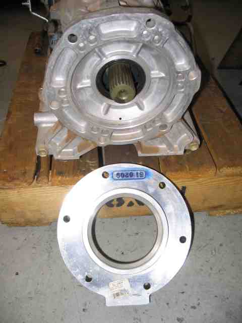
When he returned, he was holding an Advance Adapters spacer, part # 51-0404, made for a 4L60/Dana 300 combination. (The 4L60 is essentially a 700R-4 auto tranny.) Don’t even ask me why the hole pattern in the spacer actually fits that of my NP-231 transfer case, nor can I answer the question as to the spacer exactly fitting the recessed area of the AW-4. But suffice it to say that I was very glad to see that it did. I had at my disposal a “template” that was about 1″ thick and was a perfect match for the hole pattern I needed to transfer to the AW-4. It just don’t get any easier than this!
If you are going to do it, you might as well do it right the first time around. I grabbed a set of transfer bunches from the tool locker and found one that just slipped through the spacer’s hole. Transfer punches perform the same function as a regular center punch except that the body diameter of the punch is constant from one end to the other. There is a little tit on the bottom that actually does the marking/punching.
I made a pair of alignment marks on the AW-4 so I could determine proper placement once the spacer was put into place. The mark on the left indicates the centerline of where I want the new hole to appear. I only had to mark one hole since the spacer plate would located the remaining five holes correctly. You can see the mark on the edge of the spacer (top of photo) indicating the centerline of the hole.
With the mark on the spacer aligned with the new hole mark on the AW-4, it was very easy to gently tap the transfer punch to mark the exact center for the 6 new holes. I used a small C-clamp to keep the spacer from moving as I was marking the holes (sorry, forgot to take a picture of it clamped in place).
With six nice newly marked holes properly located on the AW-4, I was down to the final step….drilling the holes.
At this point, I had two options available. I could unbolt the adapter housing from the back of the the AW-4 (which was what the 6 holes were just marked on). ScottK did this (you can see it here) and it worked just fine. Doing it in this manner should pretty much guarantee you that your holes are perpendicular and go straight through since you can put the adapter housing on the drill press table. When you are done drilling the holes in the adapter housing, you will need to reseal it when you bolt it back up to the transmission housing.
I opted for the second option, which was to drill it free hand (no help from a drill press). If you suck at this, you probably want to remove the adapter housing and use the drill press.
Prior to drilling, I took several heavy paper shop towels and packed them around the output shaft. Since the adapter housing was not being removed, I knew there would be metal filings all over the place before I was done. I did NOT want them down in the seal area.
The small hole in the above photo is the pilot hole I made first. I didn’t want to attempt the full size hole from scratch. I find it easier to control the smaller drill bit and then step up the hole size to the final dimension. In fact, I used three drill sizes when making these holes. The final drill size was 13/32″, just 1/32″ larger than the 3/8″ studs on the transfer case. That didn’t leave me much room for error (or clearance) but I figured I could bump the hole size to 7/16″ on any hole that didn’t line up correctly. No reason to remove more metal than is necessary. The original holes in the AW-4 (that were used in the XJ setup) were actually a fair bit larger than what I ended up making….maybe 1/16″ or there about.
They say that the proof is in the pudding….but in this case, it will have to be the studs on the t-case fitting cleanly through the newly drilled holes in the AW-4. OH YEAH! Gotta love the way they line up. I should have bought a lottery ticket that day….I was on a role!
AW-4 Transmission Swap
As was mentioned at the beginning of this write-up, the AW-4 is an electronically controlled by a small TCU (computer) and as such, the swap entails having to deal with the electrical requirements of the transmission. Some folks are uncomfortable around electrical projects and struggle with the prospect of mounting a pair of driving lights on their vehicle. In all honesty, the electrical work for this swap is not all that daunting and if you can’t do this part of it, I’m confident you can find someone that can assist. Consulting your local 4×4 club should provide you with a body or two that can help with the wiring task.
Bob Bassett and Scott Kruize both did AW-4 swaps before I did and their efforts in documenting the wiring were very good. I got to help Scott do his swap and while he did the research for the wiring harness, I got the task of soldering it together. I remember reading through Scott’s notes and while very complete, they were a little confusing (not written the way I prefer wiring pinouts). I was also recently involved with some custom wiring on a Vortec V-8 swap into a TJ. That documentation was VERY poorly done and all that worked on the swap agreed. So….I promised myself that when I did this write-up, I would try to make a more user friendly (I hate that term but it applies here) wiring diagram. In speaking with Troy, he prefers a straight forward wiring list rather than a schematic. He said a “connect wire A to switch contact B” was easier to follow for him. So I put together a wiring list that contains the same information that ScottK provided in his write-up. It is my hope that you will find either Scott’s documentation or mine helpful. The important part is that you are comfortable following one of them so that your AW-4 project goes well.
Here is the wiring list for my swap. The first page contains the black and gray connectors for the wiring to/from the transmission itself. The second page contains the TCU connector. Scott’s AW-4 came from a 2000 XJ while mine came from a 2001 XJ. In both cases, the wire colors on the three electrical connectors were the same. Credit for the third page goes to Scott Bentley, another AW4 transplantee. (is that a word?) While we were discussing some of the details of this write-up online, it was suggested that a page covering the wire colors between the tranny and the black and gray plugs might be helpful. So that is the source and reason for page three.
Pages four and five of my wiring list are optional. I say optional because it is for making the wiring harness completely “plug ‘n play”. The 9 and 6 pin connectors are basically put in between the wires that connect the AW4 to the TJ. This means that the TJ will have a 9 pin and 6 pin connector soldered into its wiring harness too. The AW4 will have the matching 9 pin and 6 pin connectors soldered into its harness. When these two connectors are plugged together, all of the AW4 signals and TJ signals will be “cross connected”. This is the place in ScottK’s project where he used wire taps to connect the AW4 wiring into to the TJ. You do NOT have to do these two additional connectors in order to get everything to work correctly. I did them because I could and I wanted a little cleaner install under the hood. The choice is yours. I would suggest reading both ScottK’s and this write-up and then make up your mind as to how you want to do yours.
NOTE: On my wiring list, pages 1 and 2 assume that you will NOT be using the optional connectors listed on pages 4 and 5.
The wiring list for pages 1 and 2 is pretty straight forward. The connector/pin numbers on the left side of the list show the “FROM” location and the connector/pin numbers on the right side of the list shows the “TO” location. Read across one row and you will connect a wire FROM there TO here. Pretty easy, eah? If you are mildly interested (and you should be) as to what it is you are connecting, the middle column provides a description/function of that wire. Note that not all pins in all connectors are used (some are blank).
The important thing to remember when doing electrical work is to take your time and do it correctly the FIRST time. Having to go back a second or third time becomes a pain in the neck (or worse). Double check yourself several times as you locate each wire on the connector and confirm it is the correct color you are going to be soldering. Spending the extra time while constructing the wiring harness will save you a lot of time trying to diagnose a shifting issue later on.
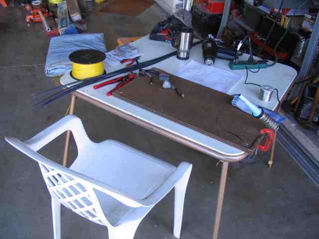
This this will take several hours to do properly (in my opinion), so you might as well get yourself comfortable. I grabbed a folding table (my wife doesn’t let me solder on the dining room table…..any more), a patio chair, and a piece of scrap particle board (much harder to destroy with a hot soldering iron than the actual table top).
A good soldering iron (or low wattage soldering gun) and a roll of rosin core solder is needed for good electrical connections (do NOT use acid core solder, like the kind used for plumbing projects!). I picked up a new wire stripper from Radio Shack just for this occasion (about $15) and I am happy to report that it worked very well. I wish I would have gotten it long ago! I also picked up several 4′ lengths of heat shrink tubing. I got tubing sizes in both 1/8″ and 3/16″ diameter. It costs about $1.50 per length so budget yourself a few extra dollars for this part of the project.
On major projects, I always try to add a little something to the tool box. While I could have used the new wire strippers to satisfy this requirement, I’ve always wanted a heat gun. I found one at Fry’s Electronics (where I bought the 4′ lengths of heat shrink) for $30. It is a dual temp (500F and 1000F) model and I’ll tell you now that it worked very well….my heat shrinking days of using a BIC lighter are long gone.
I had spent some time the previous day with a tape measure while under the hood of the TJ. I decided that I needed about 5 feet of harness to go from the end of the black and gray tranny connectors to the TCU connector. Since the TCU is not at all waterproof, I opted to mount it inside the vehicle. This goes along with it being mounted inside the XJ as well. I also prefer to have a little extra cabling rather than not enough, so my measurements take that into consideration as well. My advice is for you to select the TCU mounting location and then use a tape measure to determine the cable length that works for your needs.
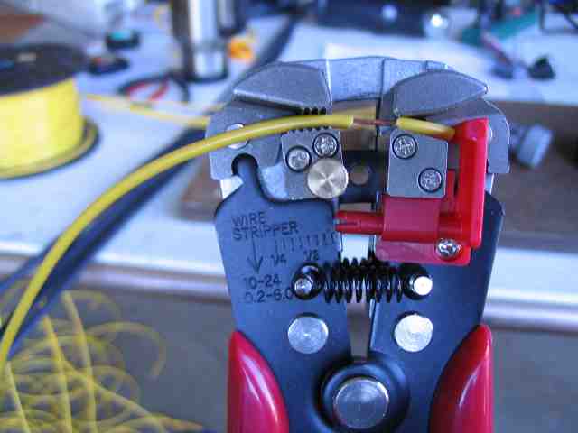
With the necessary length now determined, I sat down with my brandy new wire strippers and stripped a couple dozen lengths of wire. I adjusted the stripper to remove 1/2″ of insulation. It worked very nicely! I find it easier to do a bunch of the same steps repeatedly, such as stripping the wire….saves all that time of putting down one tool and picking up the next, over and over and over. OK….so I now have a good supply of wire.
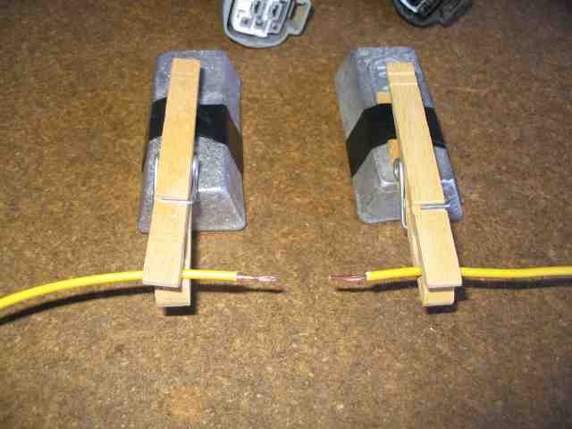
They say that necessity is the mother of all inventions. That being said, I quickly found out that I needed a third (and forth) hand to hold the wires in place while I soldered them together. I stole two clothes pins from Donna’s laundry room and grabbed a couple of 1 pound lead ingots from my reloading bench. A couple of wraps of electrical tape (sorry, the duck tape was all packed away in the TJ’s rear storage box) and my third and forth hands were ready to help. The lead bar is heavy enough to keep things nice and steady (no sliding around). A brick would have worked too but I’m not sure my old card table could have survived.
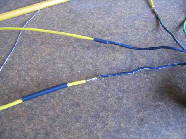
Be smart! Don’t forget to slide the heat shrink tubing over the wire BEFORE you make the connection (especially if you have a connector already attached to the other end of the wire). Hey, I only did it ONCE during the entire soldering episode….not too bad in my opinion!
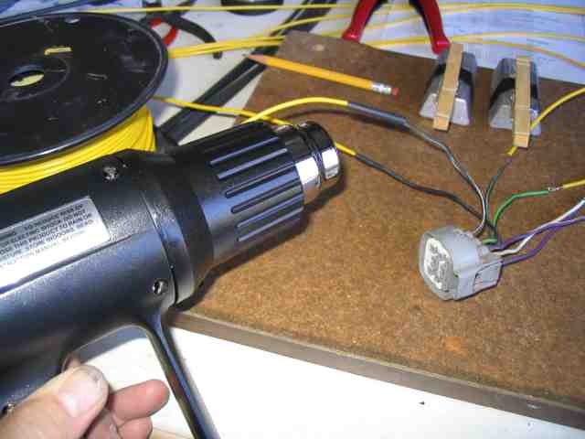
After a couple of connections were soldered, I would fire up the heat gun and shrink the tubing. That too worked very nicely. I think I am going to enjoy electrical projects much more than I have in past years. You can see the wire extensions being added to the gray connector in the above photo.
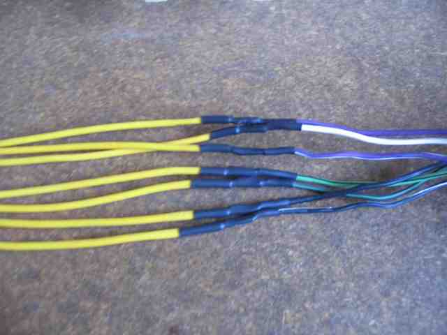
A group of wires successfully attached to one of the 8 pin connectors. After I finished the first connector, I started taping the wires together once I had 3 or 4 wires completed. It was starting to turn into a rats nest of twisted wires and that only leads to making mistakes and an overall messy work space.
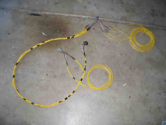
Here is the harness after a couple of hours of work (not yet completed). The two coils of wire will be finished later on this week when I get some more time. They are the wires that will be going to the TJ’s wiring harness. The 9 pin Molex connectors I got at Radio Shack will be used for this section of the harness (pages 4 and 5 of the wiring list). Once it is all completed, I’ll wrap it completely in electrical tape and then slip a plastic wire loom over it to prevent any abrasion.
AW-4 Transmission Swap
OK, it is now later in the week and time to identify/locate the physical wires in the TJ’s wiring harness that will be interfaced to the AW4 wiring harness. Assuming you already looked at my wiring list, you should have noticed that some of connections go to various TJ wires to provide +12V, ground, throttle position, brake pedal switch, etc.
After looking at the various connections that were needed, I opted to tap into the TJ wiring harness near the PCM (Powertrain Control Module). This is one of those times when a factory service manual is very good to have available. There is a plethora of information contained in the wiring diagram section.
One thing I noticed, when reviewing ScottK’s write-up, was the difference in the PCM connector designations between his diagrams and mine. At first, it kind of threw me for a loop and then I realized his pin-out diagrams were that from the XJ service manual while mine were obviously from my TJ manual. While the signal functions and wire color are the same, the actual connector designators are different between the two vehicles.
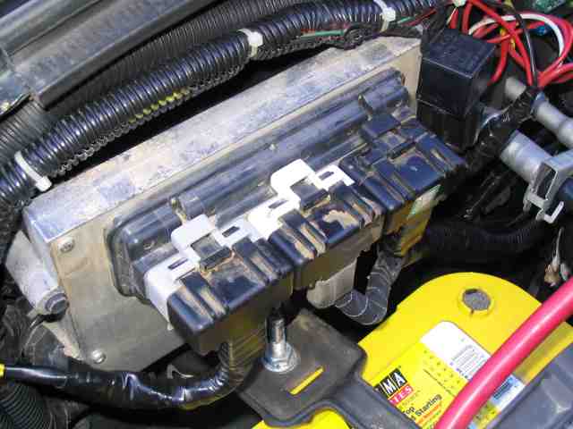
The connectors on my 98 TJ’s PCM has three plugs (as all do) and they are different colors; gray, white, and black (shown left to right in the above photo). In my wiring list, I listed the connector color as this seems less confusing than using the C1, C2, and C3 that they are also known by in the factory service manual (and which conflicts with the designators that ScottK used in his write-up). Again, this is where having a factory service manual for your year vehicle really pays off.
Rather than try to chase the wires around the vehicle’s wiring harness, I opted to tap into the necessary wiring fairly close to the PCM connectors.
Note: Time to disconnect the negative leads from the battery if you have not already done so.
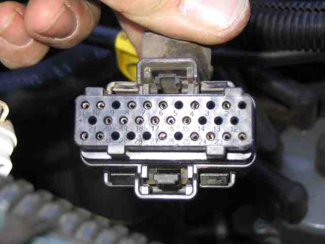
Here is a picture of the black plug disconnected from the PCM. As you can see, the pins are numbered, which makes it pretty simple to reference this end of the connection.
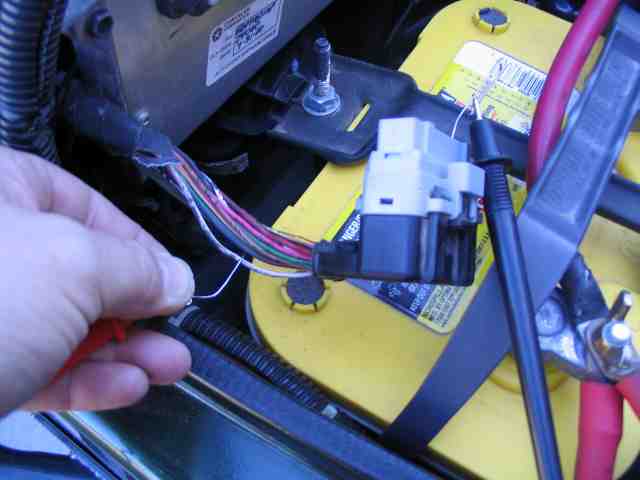
I used an ohm meter to positively identify the wire in the harness. Since my test leads were too large to fit into the connector, I used a paper clip to make contact with the connector pin. I used another paper clip that had been sharpened to a fine point. It easily pierced the insulation on the wire I wanted to test. So with the paper clip inserted into the correct pin on the connector (and the meter lead attached to the paper clip), I located and identified the wire by its color and then checked that by testing it with the ohm meter. A short (0 ohms) tells me I have located the correct wire in the wiring harness.
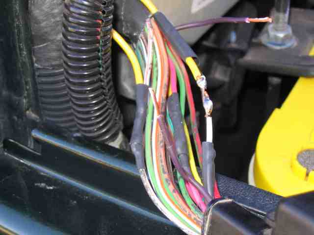
With the wire properly identified, I cut it in half, stripped the ends back about 1/4″, and then spliced the new wire into the connection. I used heat shrink tubing to seal up the new connection. (Make sure you slide the heat shrink onto the ends of the wires BEFORE you solder them together.)
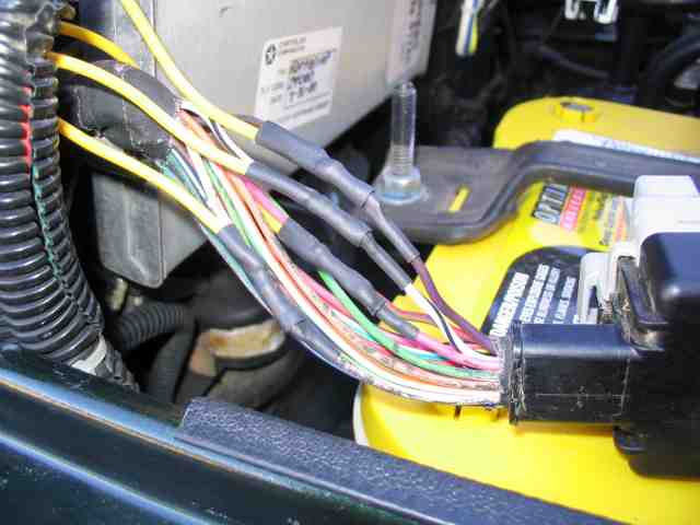
Here are the 4 splices made at the base of the gray PCM connector. Nice and neat, minimal impact on the remaining wires in the harness. As each splice was completed, I attached a label to the wire indicating the pin that it was connected to. When all of the splices were complete, and the vehicle wiring harness was re-taped, I was able to identify each wire by the attached label.
AW-4 Transmission Swap
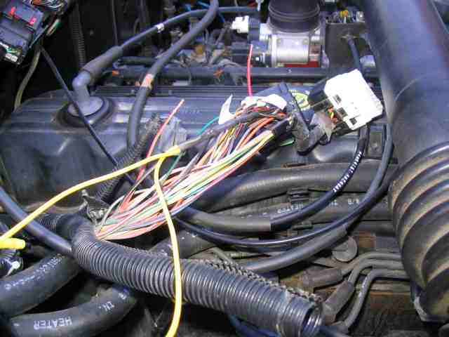
The connections going to the black PCM connector were done in the same fashion as the gray connector. The white and black plugs share the same main wire harness and it is quite a bit larger than the harness going to the gray connector. As such, you have to dig through the wire harness a bit more to find the correct wires for the splice. I removed the plastic loom material for about a foot and stripped off the tape so I could access the wires. I used the ohm meter to ensure I had selected the correct wire, then cut it, stripped it back, then soldered the splice wire. As before, heat shrink tubing was used to seal up each connection.
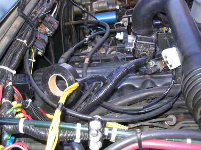
With the splices all complete, I used electrical tape to patch up the area where I had to remove the factory wrap on the wire harness. I also taped together the sliced wires where they came out the TJ wire harness. From here, they go to a couple of connectors that turn this into a plug and play setup. (more on to follow) Take your time and it should come out just fine.
When we built the AW-4 harness for ScottK’s TJ, the connections were made directly between the two harnesses. While this worked and was very reliable, it made it difficult if you wanted to isolate a wire for troubleshooting purposes. Likewise, if you ever had to remove the AW-4 harness for some reason, it meant you had to go in and either cut or unsolder the wires from the TJ harness.
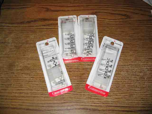
I wanted a little more flexibility in my configuration. A visit to the local Radio Shack store provided just what I needed. I purchased two pairs of connectors, a 9 pin male (# 274-229) & 9 pin female (# 274-239), and a 6 pin male (# 274-226) & 6 pin female (# 274-236). I would use the 6 pin connector to make the CCD + and – and SCI transmit connections between the TCU and the TJ. Since ScottK determined these cause the check engine light to illuminate when you use the shifter, this plug will normally be disconnected. If I want to to query the TCU with the OBDII scanner, I can connect the two plugs. The 9 pin connectors will be used to connect the remaining wires from the TCU and the transmission range sensor (gray plug).
Note: The above plugs are those referenced on pages 4 and 5 of the wiring list.
Note: I originally bought a 4 pin male & female connector, but the male connector came with the wrong diameter pins. As such, the two connectors would not plug together. So, it was back to Radio Shack to exchange them for the 6 pin versions. I’ll have three unused pins in the connector.
AW-4 Transmission Swap
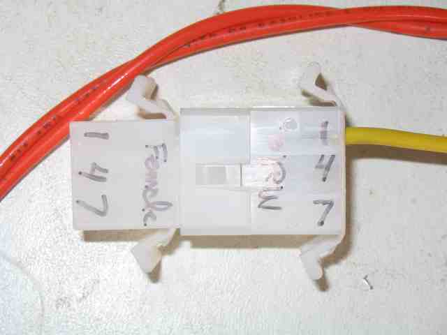
I started with the 9 pin connector. Plug both halves together and mark the pins so you don’t get them messed up. Once the individual pins are pushed into the connector body, they are virtually impossible to remove without destroying them. I got distracted when doing pins 6 and 7 and got the two exchanged (DOH!). Rather than screwing up the pins, I cut the wires and then spliced them back together (it happens).
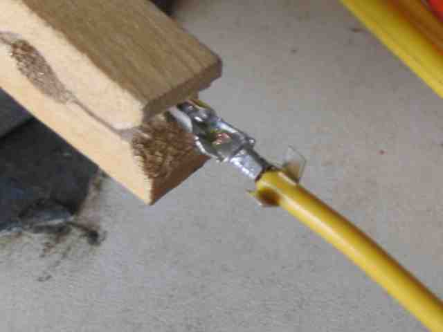
I used the clothes pin again since I still only had two hands. After stripping a 1/4″ of insulation from the wire, I crimped the pin onto the wire using a pair of needle nose pliers. I then soldered the pin to the wire and finished it by crimping the tabs over the insulation.
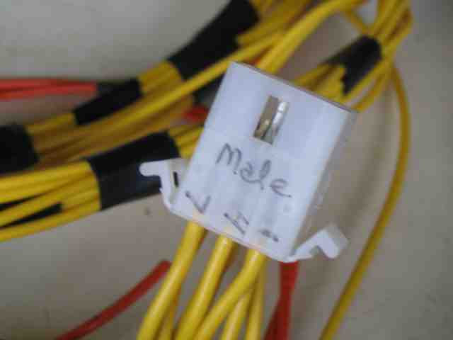
The pin, after being soldered to the wire, was then inserted into the plug. Did I mention you want to be sure you get it in the proper hole?
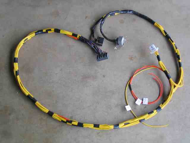
You can see the 9 pin connector now in the harness. The three wires not yet connected will be attached to the 6 pin connector. The harness is starting to take shape and it is beginning to look like the real thing. As I mentioned earlier, I will wrap it with electrical tape and put it in a wire loom before permanently installing it on the firewall with tie-wraps.
I was asked how long my harness was. From the TCU plug to the two tranny plugs (black and gray), it is 6′ long. The 6 conductor plug is 4′ from the TCU end of the harness. This length provides adequate harness length to mount the TCU under the dash (driver’s side kick plate area). When you make yours, I suggest you break out the tape measure and check to see what your requirements will be, then cut your wires to the appropriate length.