Now we start getting into the fun part of the project. I’m not going to go into a lot of detail on the steps necessary to remove the AX15. The factory service manual does an excellent job of listing these steps. I’m just going to give a quick overview and list a few snags that I ran into.
- Remove the interior console and shift boot. Then unbolt the shifter housing from the top of the transmission
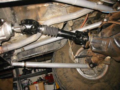
- Remove the front and rear drive shafts
- Remove the starter
- Support the motor and transmission using floor jack under oil pan
- Remove the cross member
- Unbolt the transmission mount
- Disconnect the transfer case linkage
- Disconnect the speedometer plug at the harness
- Remove the transfer case
- Support transmission using tranny jack. (I highly recommend that you borrow or buy one. I bought this one at Harbor Freight for $69.)
- Remove external clutch slave cylinder
- Unbolt dust shield bolts (Some of these are hard to see. If you don’t remove all of them you will find yourself cursing at the point you try to free the tranny from the engine.)
- Remove bell housing bolts.(The top 2 bolts require reverse torx sockets. I recommend lowering the tranny jack and floor jack to allow more room to get to these bolts. You can replace these with standard bolts if you like.)
- Remove the transmission. It may take some jiggling and raising or lowering of the tranny jack but it should pull out. (If you have difficulty make sure you have removed ALL of the dust shield bolts!)
- Roll the tranny out from under the Jeep.
- Unbolt the clutch and flywheel from the crankshaft.
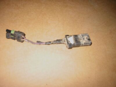
***There is one more little step that we can’t forget to overlook. Look at the wiring harness where the AX15 once was. Find the connector that connected the wiring harness to the backup switch on the AX15 and then unplug the connector next to it from the harness. This connector does 2 things. First it completes the circuit for the backup lights. Second it is the manual transmission neutral safety jumper. We need to completely remove this from the TJ for good. It provides a ground and bypasses the neutral safety switch. Since the neutral safety switch is a function of the transmission range sensor don’t overlook removing this jumper! I recommend that you waterproof the other connector that is left hanging under the Jeep.
ALL DONE!
Bolting in the AW4
Now we are really starting to get somewhere. Let’s walk through the steps necessary to bolt this baby in! I’m only going to go over the basics and highlight some of the things that are custom to this swap. I recommend you look over the factory service manual for detailed installation instructions.
- Install the AW4 dust shields to the engine block. They will fit over the alignment pins. (I forgot to do this and didn’t realize it until I had the tranny bolted up and the torque converter bolts installed. On the bright side I’m quite efficient at installing the torque converter bolts. 🙂
- Cut off the exhaust hanger that is just in front of the catalytic converter. (The hanger interferes with the installation. This will save you a lot of trouble. You will have to weld in a new hanger when the project is complete. As you can see in the picture below I learned this hard way. Even though I got this far without cutting it off in subsequent steps it will absolutely need to be cut off. It’s a lot easier to do before the AW4 is bolted in.)
- Install the drive plate and spacer. Rotate it until the bolts line up. There is only one way to install this.
- Bolt the bell housing to the engine block.
- Install the 4 torque converter bolts. I would recommend that you line up your holes on the drive plate with those on the torque converter prior to lifting the AW4 into position. This will make it alot easier to find the first hole.
- Torque the bolts per the FSM.
- Install the CPS
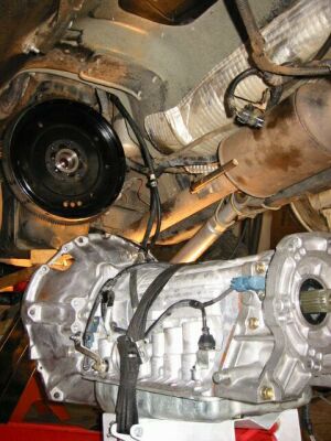
It should now look something like this:
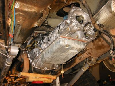
Now you will want to bolt up the transfer case. Once that is complete you need to fabricate a plate for the tranny mount.
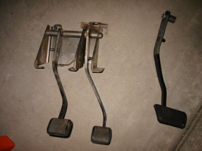
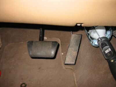
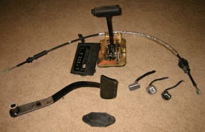
Brake Pedal
At this point we need to look at the shifter assembly and brake pedals. I started with removing the brake and clutch pedals. Boy this was a real pain! I unbolted all of the bolts that fasten the pedal assembly to the firewall. Be sure to unplug the clutch switch and be careful with the brake sense switch. From under the hood pull the master cylinder and clutch cylinders back. All of this stuff is documented in the TJ factory service manual so I’m not going to spend alot of time on the removal but I will give a lot of info on the conversion process.
Here is a picture of the pedal assembly removed from my TJ. You can see the auto pedal that we are going to install.
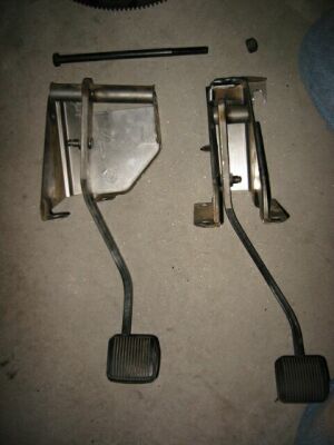
Here is a picture after removing the long bolt that holts the pedal assembly together. It was interesting to find out that the pedal assembly was modular. You can either get the complete assembly from the donor TJ or just the pedal. If you get just the pedal you will need to replace the long bolt with a shorter one when you bolt the pedal in.
Here is a picture of the reassembled pedal.
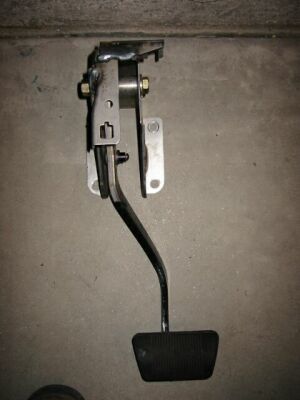
And here is the finished product. You may find that the pedal does not contact the switch when the install is done causing the brake lights to stay lit. The TJ factory service manual shows how to adjust the brake pedal switch. I recommend that you look this up.
***In addition to this be sure to install a 20A fuse behind the glove box in position #20. This is the clutch interlock ignition bypass. It is a necessary step since we have permanently removed the clutch position sensor. Failure to do so will result in the Jeep not starting!
Cooler
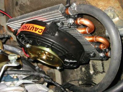
It’s time to deal with the cooling issues. Here is a picture of the Flexalite cooler that I purchased. As you can see it has an integrated cooling fan.
Here in Arizona cooling a big problem in the summer months. When its 115 degrees out with the AC on max the radiator and condenser are at full capacity to keep things cool. I have already upgraded every single cooling system component including an electric pusher fan.
Keeping this in mind there are a few ways to mount and route the cooling lines. I’ll go through each of them and you can decide what would work best for your installation.
- Plumb the cooling lines into the radiator. My 3 core radiator can also be used as a tranny cooler. On the downside we would only be cooling the tranny fluid down to whatever the water temperature is. I have also read that this can add 20 degrees to the cooling system. In most climates this is probably ok. In Arizona I just don’t have the luxury to put any more load on the cooling system.
- Mount an auxiliary cooler in front of the radiator. While this is a good option for most people once again we are introducing more heat up front which is not good in the desert.
- Mount a remote auxiliary cooler. Now we are talking. We can cool the tranny fluid without introducing any more heat up front. This sounds like a good solution for the desert.
- Combine a front mounted cooler with a remote mounted cooler.
I chose to go with a remote cooler due to the high temperatures we experience in Arizona. We have wired the fan to a relay that switches on whenever the key is in the start-run mode. You may chose to have a manual or thermostatically controlled switch. It’s entirely up to you and your needs.
Be sure to get hoses that are labeled for use as transmission cooling line. Other rubber hoses cannot handle the high temperatures that they see. I used 1/4 NPT barbed fittings and 5/8″ hose clamps.
Where you mount it is your choice. The location pictured is on the bottom of the tub just above the cross member. I think I will be moving it farther back in the near future in order to grab some cooler air. (Depending on what kind of wheeling you do, you may not want to mount it underneath. Efficiency is lost if it gets covered in mud.) Like I said earlier, this is entirely up to you.
Getting ready to bolt up the cross member
We have test fitted the cross member while fabricating the tranny mount so we know it will fit. Before we bolt it in there is a couple things we need to do.
- Change the tranny filter
- Reinstall the oil pan
- Cut down the XJ cooler lines and install the 3/8″ compression fittings so they look like this:
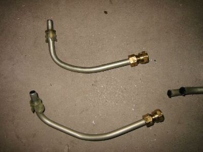
- Screw the barbed fittings into the cooler lines then snap the cooler lines into the transmission
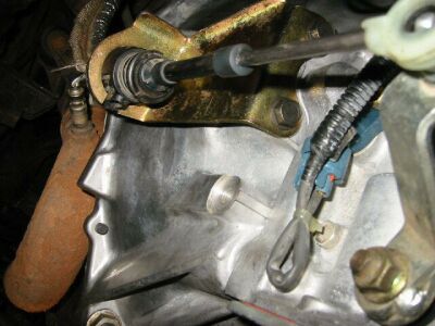
- Install the AX15 transfer case linkage bracket. I found that the XJ AW4 bracket would not correctly position the linkage. Use the TJ bracket and bolt it to the transfer case studs just like it was with the AX15.
- Modify the transfer case linkage. We need to drill the bracket that is bolted to the tub. I drilled new holes 1″ farther back on the bracket. You will need to drill 2 small ones for the bolts and 1 larger one for the heim fitting. Ideally I would recommend that these holes be drilled 1.5″ inches farther back. (I misplaced the picture that I took.)
- Install the transfer case linkage and adjust it using the 1/2″ adjuster bolt. Refer to FSM for more details.
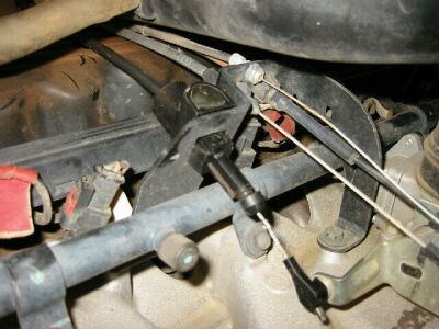
- Install the shifter bracket and snap the shifter cable into position. Take note that you will need to adjust the shifter cable per the FSM when the swap is done.
- Remove the throttle body return spring and snap in the kick down cable that is attached to the AW4. It will look like this:
- Install the dipstick tube and dipstick.
- Now you can bolt up the cross member and install the transmission mount nuts.
Final Steps
We are now up to the final steps of the swap. Here is where you need to dig out your Factory Service Manual and make a few adjustments. I will outline these things and provide extra detail where necessary.
- Adjust the kick down cable
- Adjust the shifter cable
- Install the starter
- Install your front and rear driveshafts (Check the lengths carefully, you probably need to have the rear shortened and the front lengthened)
- Check rear pinion angle and adjust if necessary
- Adjust the brake sense switch located by the brake pedal
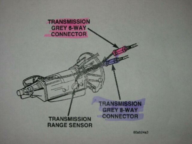
- Make sure your tranny harness is plugged in to the TCM, gray 8 way, and black 8 way plugs.
- Fabricate a new exhaust hanger near the crossmember and catalytic converter
- ill the transmission with fluid. I used 7.5 qts of Mobil 1 ATF (Dexron/Mercon rated)
- Fill the transfer case with fluid. I used 1.5 qts of Castrol ATF+3 (You need to use ATF+3!!!)
- I’m assuming you already routed and tied up the harnesses above the transmission and transfer case. This includes the transfer case and transmission breather lines. Be sure the breather lines are up on the firewall.
- Adjust the Park/Neutral (TRS) switch (If it will only start in Park and Neutral then skip this step)
AW4 Swap into Daddy Longlegs
“How I swapped a 4 speed automatic from a 2000 Cherokee into my 1999 Wrangler”
by Scott Kruize – Avondale, Az
October 2002
Wiring diagrams TRS – Gray 8 way plug
Wiring diagrams Solenoids – Black 8 way plug
Wiring diagrams TCM – Black 26 pin plug
Wiring – Tying into TJ harness (Part 1)
Wiring – Tying into TJ harness (Part 2)
Wiring – Pics of the harness in progress
Pilot bearing and bushing removal
Getting ready to bolt up the cross member
Introduction
It all started when my wife and I were coming home from celebrating our 1 year wedding anniversary. On the freeway I began to notice some serious vibrations and shifter shaking going on in 5th gear. I shifted down to 4th and things were a little better. I got off at the next freeway exit. I crawled under my Jeep and noticed oil on the cross member. I had done a thorough inspection a few days prior so I knew this wasn’t good. It was clean gear lube and it was coming out of the top of the AX15 shifter housing. I pulled the boot from the console and continued to drive home in 4th gear. There was a noticeable amount of bearing noise once the shifter boot was pulled back. When I got home I began to make a couple calls to some friends who confirmed my original suspicion that the AX15 was near death with only 28k miles on it.
I knew that I wasn’t going to put another AX15 in. It was either an NV4500 or an automatic. Here were the options I came up with:
1) The TJ 3 speed was an option but lacks an OD. Cost for swap $700-800.
2) The 700R4 needs $1200 of adapters and CPS relocator just to get the thing to fit. That’s before you even factor in the cost of the tranny.
3) An NV4500 would be the easiest swap but it was still a manual. Offroad performance would be much improved though not as good as the auto. Its about $2800 to get the NV4500 and parts needed.
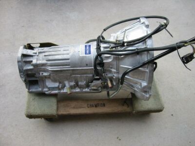
4) The Cherokee AW4. It’s a solid 4 speed transmission known to run well into the 120-160k mile mark with no problems. It has been used in Cherokees 87-2001. It was also used by Toyota in Four Runners and Supras. Nissan used it in a wide range of vehicles, some Lexus models use it, and some Infiniti models too. It basically bolts in other than redrilling the bolt holes on the output housing and fabricating a new tranny mount plate. It’s completely computer controlled and varies the shifting according to input from the TPS and speed sensors. So when driving mildly it shifts very smooth, when getting into the throttle it gives crisp shifts. It’s only 1″ longer than the AX15. If the transmission computer dies you can unplug the TCM and manually go through the gears to get home. Cost is $650, throw in another $400 to get the TCM, shifter assembly, pedal, cables, and tranny cooler and you have a low mileage 4 speed with around $1000 into it.
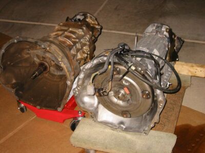
The choice ended up being between the TJ 3 speed and the XJ 4 speed AW4. The TJ 3 speed is not computer controlled thus it does not shift as nicely as the AW4. Stu Olson and I picked up the AW4 on a Monday afternoon. This one is out of a 2000 Cherokee with less than 20k miles. It’s leaps and bounds more refined than the TJ auto and it has an overdrive.
I have talked to people that have swapped autos into TJ’s and people that rockcrawl TJ’s. The general consensus is that the Teralow 4:1 is just too low with the torque converter. Therefore I decided to sell my Teralow and roll that $450 into the swap. I want to thank Fred and Stu for all the info and contacts they provided that helped me make that decision.
This swap is done by AEV conversions. They are the ones that take brand new TJ’s and stretch them. They were of no help to me. I have never received a response back from them.
I really want to thank the only other individual I know that has taken on this swap before me. That is Bob Basset of California, also known as Scratch on JU. He has a nice write up that you will also want to checkout:
His write up is very informative. I’m hoping that my write up will improve upon his in 2 key areas. The first being the wiring portion of the swap. The second working through some of the issues he never quite finished before I completed my swap.
Links
Misc AW-4 Information
The following comments were extracted from a thread on JeepForum.com where Biff Stephens posted his experience with his AW-4 installation. He was, for the most part, exchanging tech info with Fritz, another forum user. I obtained Biff’s permission to include them here as they will be easier to locate for all who are looking for AW-4 swap info for their TJ.
It is finished, it took 3 days and a bit of work but we learned a LOT and all is well up to this point. I have some pics but not here so the post will be dry for a while. I will post my thoughts and road blocks we ran in to while doing it.
First of all, there are 2 great write ups I used for this. They are below. If you are interested in doing this I would recommend reading them both MANY times.
http://www.thebassetts.us/Jeep/AW4/AW4_files/page0001.htm
http://www.stu-offroad.com/engine/aw4.htm
Removal…..went without a hitch doesn’t it always? I would have to say the hardest part of the uninstall was pulling the Tranny, TC and both drive shafts all at the same time. We had some hands so it was not all that bad.
Next was the taking the TC apart to get the input gear out to get it shortened. This was not all that easy. You pretty much have to take apart the whole TC and remove the shaft. I guess I had missed the complexity of this in the write up. For someone that has does a TC rebuild I am sure you will have no problems.
Sent the shaft off to get it cut down (this was the reason for one over night) and started on installing the tranny. This went pretty well with no issues.
We decided to do the wiring in the morning of the second day. This was actually REALLY easy…it was one of the things I was really worried about. The key I feel is I have the complete wiring harness for the XJ the tranny came out of…..We removed it from the harness without cutting many wires and all the colors matched and were already connected. We did have to lengthen the harness but this was not an issue at all. After this, there are 9 (I think) wires to tie in to the TJ harness.
Got the input shaft back at noon the next day. This is where we started to have issues. We put it back in and went to put the case up and it would not go in. Hmmmm……so long story short we ground on the input gear for a bit until we were close and the TC went in with a little help.
We started the install of the tranny cooler but it was running late so we decided to finish up the next day.
The next day was making sure all the T’s were crossed and I’s dotted. Tranny cooler, drive shafts, tranny and TC fluids, shifter and whatever else I forgot.
So the time has come…..starting it…..turn the key…..no start…..I did not have a clutch in SO the clutch safety switch was not activated. So I did the mod where you add the 20 amp fuse and it turns that off.
Waa Laa…..
Everything started and ran fine. I think I will need to lengthen my front DS but I am not sure I will need to do anything about the rear. I might need to re-point my pinion angle.
All is good and I am very happy with everything. I cant wait to go wheeling again to try it out.
I am tired so if I forgot anything give me a break. I will try to add it.
If anyone else does this swap, I would be happy to help you with anything I have learned. Anything short of grinding that input gear.
Good luck,
Biff
I had one concern when I read what you posted about mounting your np231. How much clearance did the input shaft have before it bottomed out? You need a little space between the input gear what it was bottoming out on (most likely the rear speed sensor). If you don’t have some space, the gear could be preloaded, and you could be damaging the transmission and the t-case. Just something to be aware of.
Have fun with your new tranny!
__________________
Fritz
I just took it on its first 50 mile drive. Everything is going really well so far. I am interested in the D300. I really like the twin stick option. I can’t afford an Atlas really and as you said the D300 has an upgrade path.
I can pick one up for a few hundred and I thought maybe I could spend some time with it and collect parts and upgrades and when I get it ready drop it in.
About the input shaft. I will go into more depth. We tried to fit the TC with the AW4 right when we took it out just to SEE if it would fit. It did not, of course, so we sent the input gear off to get it machined.
Here is my screw up.
“Here are the measurements from the snap ring after the input shaft was removed. Short shaft is 1.350 where the long shaft is 2.100. These numbers were confirmed by Advanced Adapters.”
That is a quote from Bob’s AW4 swap…if you take 1.35 from 2.1 you get .75. So I sent the shaft off to get 3/4″ taken off. It cost more than I had planned but it was done and I was ok with that. We get it all back together and go again AND it is still hitting. It just was not making sense. It was very perplexing……so I found this…
http://www.novak-adapt.com/knowledge/np231.htm
Down the page, it pretty much states that the difference between a long and short shaft is .9″.
So now I thought I had not ground enough…..so we started grinding. This went well…..we did not heat it up a lot, went slow, and used lots of cooling water. It still would not mate up.
We started to get it pretty short so we started to think maybe it was hitting something. We “think” that it was hitting the rear seal of the AW4. Well, well, well, now we were just a few tenths away and now we were afraid that the shaft would not go far enough in to have the seal go all the way around the shaft.
So we put a few bolts on the TC and started to pull it together…..all went well and it did go together with not too much effort.
I guess I screwed up but I am not sure……it seems to have worked. We also decided not to re clock the TC as well. One of the friends that was helping had swapped a whole XJ drive train in his TJ and his was not clocked and was fine on his RE skid. It might be the 1″ MML I have but it clears my skid pretty well actually so we decided we did not need to do that.
I think I will stick with my small brake pedal. At the least I might weld the clutch to the brake pedal. I am not sure right now…..we shall see.
So it is still in progress…..a lot of we shall see’s.
Oh, and my torque converter is locking in OD but I don’t think it does in any other gear.
I hope all of this info helps somebody…..LOL
Biff
Ok, well that sounds like the input gear is probably all right then. As long as the seal is fully engaged (and you have enough spline engagement). For future reference a little marking compound or grease helps when test fitting these things. Makes it easier to see were things are lining up, what is hitting what, etc.
To test your convertor in 3rd gear. Get up to speed (in 3rd of course). While holding your speed, tap lightly on the brake pedal. You should notice a slight (couple hundred RPM) change in the rpm. When you release the brake pedal the rpm will drop back down. I think the convertor will lock in 2nd too, but I am not sure and it would be hard to test using the
above method. I would be mostly concerned about 4th and 3rd lockups.
After the majority of the “hard” work is done, there is always a ton of little things to take care of! BTW, the junk yards are full of jeeps with automatic pedals.
HTH
__________________
Fritz
I just wanted to report that everything is working well. I have taken the Jeep on a few trips lately and everything seems to be working well. At this point, I need to start cinching up some loose ends I have. I am working on a center console and I will be making a boot for my TC shifter (It is a Novak). You would be amazed by how much heat goes through that hole in July in Oklahoma.
Another loose end, so to speak, is the reverse lights. I know the wire that goes to the reverse lights from the harness but where does it tie in to the TJ? I read over (scanned) the write up again but did not find it.
Any ideas would help.
Thanks,
Biff
Hey Biff, glad everything is working great so far. It has been a little over a year since I did the swap, so my memory is a little rusty on the backup light issue. But I’ll try to get you pointed in the right direction. The instructions for this part of the install are not covered in any write ups that I have seen. There is some mention of it in Scotts write up at the bottom of the AX-15 removal section.
The backup sense for the TCU is on pin 18, and is a BR/LG wire. It receives it’s signal from the Transmission Range Sensor. This tells the TCU that the transmission is in reverse. This is the wire that needs to be tied into the TJ harness.
On the TJ, the backup switch for the AX-15, there was a jumper that was removed that went to the backup switch. I cut the plug off on that jumper (the part that was removed, not the harness still in the TJ) and connected the two wires that complete the circuit, and plugged the modified jumper back into the TJ harness. As if the former AX-15 was in reverse, bypassing the old switch. I believe the wires were VT/BK and VT/WT.
Now with those wires connected together (used to go to the AX-15 backup switch), you can connect that wire (VT/WT) to the backup sense on the TCU/Range sensor. I believe you need to cut the VT/WT wire and connect it to the backup sense. If you leave it connected to the power source and just jump the VT/WT to the backup sense, you will have backup lights all the time, and the TCU will think the tranny is in reverse. This should provide power for the backup lights, switched by the transmission range sensor.
This is basically how the Cherokee is wired up. I was fortunate enough to have the FSM electrical sections from a ’00 XJ, and ’97 TJ, so I was able to figure it out from the wiring diagrams and pin-outs.
HTH
__________________
Fritz
OBD2 Comments
I learned a whole lot about the OBD2 systems while researching and doing this swap. I was fortunate to own an OBD2 scanner. This really helped me work through some issues.
I had been fighting an OBD2 code I kept getting from the tranny. (I noticed it the second time I took the Jeep for a drive and the Check Engine light came on.) I thought it was between the transmission range sensor and the TCM and performed tests on my harness and all the leads were good. I then tried another TCM and I got the same code. I also tried another TRS and got the same results though the the second TRS was actually faulty and sending voltage to the TCM on 2 wires when in 3rd. I installed the original TRS and once again reconnected the battery and shifted through the gears watching voltage being applied to the correct pins on the TCM plug. I did every test imaginable and everything tested out good. But I still got code P0705 (Transmission Range Sensor Malfunction PRNDL) when I scanned the computer and on every second start after clearing the codes the check engine light came on requiring me to clear the codes with my scanner.
Here’s what I think is happening. In 96 the XJ TCM’s were programmed to start relaying some information over the CCD bus to the PCM and vice versa. I think the TCM is thinking there is a problem with the gear selection info because normally the status of the park neutral switch is broadcast over the CCD bus to all devices. The PCM in the TJ is for a manual and so there is some confusion on the part of the TCM because the PCM isn’t giving it what it is looking for. The CCD bus + and – circuits are for communication between all of the OBD2 devices in the vehicle including PCM, TCM, airbag module, and sentry immobilizer key. All of these devices have a SCI transmit wire going to the Data Link connector though the PCM also has a SCI receive wire. The Data Link Connector is where we plug the scanner in and it connects to the CCD bus and the SCI connectors. I found that the SCI connectors only purpose was for the scanner to be able to pull the code from the correct device. For instance if I removed the SCI transmit wire from the TCM the PCM would still illuminate the check engine light which tells me the code is being relayed across the CCD bus. But if you then try to scan for the error code you get nothing. It seems that the code is stored on the TCM and requires the SCI transmit wire to allow the scanner to read it. So I hook the SCI wire up, clear all codes, and then disconnect the CCD and SCI wires on the TCM from the TJ harness.
Here’s what happens…it runs perfect!! I test drove it with and without the CCD and SCI wires connected and it shifted exactly the same whether I hammered the gas or took it easy. It braked exactly the same and idled the same. The best part was that I no longer get any error codes when I scan the PCM. The PCM is happy thinking it still has a manual tranny behind it. It gets RPM info from the tach, and output speed info from the speedometer and its happy like before the swap. Now the TCM I think is getting everything it needs too. The tranny has its own input and output speed sensors. So the TCM knows the engine RPM, and of course the output RPM’s. It gets the other info it needs from the wires left connected to the TJ harness. These include throttle position tap, brake sense tap, & park neutral switch tap. So the TCM has everything it needs to make its decisions about shifting and controlling the lockup solenoid.
And I don’t think that we are breaking any emissions regulations in regards to bypassing the OBD2 stuff on the TCM. Our TJ’s never had any OBD2 controls on the tranny prior to the swap so technically I don’t believe we are required to integrate the OBD2 TCM into the data link connector.
Now if for some reason the tranny is misbehaving and you want to pull other codes from the TCM all you have to do is hook up the CCD + and – as well as the SCI transmit wire. Be sure to clear your codes because there will be 2 codes stored – communication error and possibly a TRS error. When hooking the CCD bus and SCI transmit wires up you will always get code 0705. Ignore that code. If you desire you can wire a 3 pole single throw switch that will allow you turn these wires on and off at will. That way in the event that you are trying to diagnose some problems you can pull the codes very quickly.
Parts List
- XJ AW4 transmission
- XJ Drive plate and spacer
- XJ Dust shield
- XJ shifter bracket that bolts to trans (gold bracket in first picture)
- XJ Transmission Control Module
- XJ tranny mount and plate (I did not use these)
- Bellhousing bolts
- Torque converter bolts
- Other miscellaneous bolts
- TJ shifter cable
- TJ shifter assembly
- TJ shifter tub plate (not pictured, bolts to tub then shifter assembly bolts to plate)
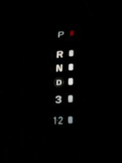
- XJ shift indicator panel (P,R,N,OD,3,1-2)
- Be sure to get the light assembly that goes with the indicator panel.
- TJ automatic brake pedal (or you could just keep your current pedals and weld them together)
- Clutch cylinder plug plate (to plug the hole in the firewall where the clutch cylinder was)
- Black 26 pin plug (Transmission Control Module)
- Gray 8 way plug (Transmission Range Sensor)
- Black 8 way plug (Shift solenoid control)
- XJ Transmission cooler lines (not shown here)
- Transmission cooler (not shown here, I used a Flexalite cooler with integrated cooling fan)
- 3/8″x1/4″ NPT compression fittings to adapt cooler lines (not shown)
- Rubber tranny cooler hose and clamps
- Short 23 spline input gear for the NP231
The AW4 is around an inch longer than the AX15. This will probably require you to lengthen your front driveshaft and shorten your rear driveshaft. I recently did an axle swap and switched from an RE hack ‘n tap SYE to an Advance Adapters SYE. My rear driveshaft is actually 2 inches longer than it was before. My front driveshaft was lengthened almost 2″. Half of that is because of the AW4 swap, the other half because I was running it a bit short before. Keep this in mind. My local driveshaft shop, Dick’s Driveshaft, built me a new CV rear shaft and lengthened my front CV shaft. Please see the table below for a breakdown on the cost of the swap.
| AW4 Transmission – 20k or less |
$650.00 |
| TCM |
125.00 |
| 23 Spline short input gear |
125.00 |
| Auto-meter trans temp gauge |
40.00 |
| Flex-a-lite cooler, hoses, clamps |
145.00 |
| Transmission filter and Mobil 1 ATF |
57.00 |
| Miscellaneous – ATF+3, 1/4″ plate, bolts, etc |
20.00 |
| Advance Adapters HD SYE (replaces RE SYE) |
275.00 |
| New rear CV driveshaft, front lengthened |
325.00 |
| Sold Teralow 4:1 |
-450.00 |
| NP231 front bearing and seal |
26.00 |
| Total Cost of swap |
$1338.00 |
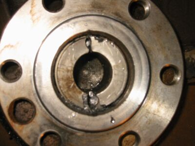
Pilot Bearing and Bushing Removal
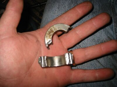
If your TJ has a manual transmission you will need to remove the pilot bearing and bushing from the end of the crankshaft. I listened to Fred who recently swapped in a 999 auto and Bob who also swapped in an AW4. Both of them used a chisel to break it. I thought I’d try something different. I drilled 2 holes not quite as big as the bushing is wide into the bushing. Then I used a sharp chisel to break the bushing at the holes. It worked like a charm. Once the bushing and bearing are completely removed use a small file and some very light sandpaper to make the inside surfaces smooth again.
Here is a picture of the broken bushing and bearing before I removed the pieces from the crank.
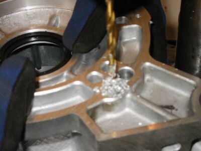
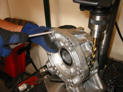
Redrilling the AW4 Output Housing
There is an interesting difference between how the transfer case mounts on the TJ vs. XJ. The Cherokee uses a 23 degree rotation on the transfer case. On a Wrangler there is a 13 degree rotation. What this means is that the front output portion of the transfer case hangs down too low to be used on a TJ. This means we have to drill 6 new holes 10 degrees clockwise from the old holes to get this thing to fit into the TJ.
You have 3 options here.
- Take it to a machine shop for probably $60 or so.
- Buy a clocking ring. This will add 1/2″ to the driveline length and costs $125-190.
- Drill ‘Em yourself!
We chose the third option. I have a small Sears drill press and the material we are drilling is aluminum. Stu and I measured many, many times before we felt confident enough to drill the holes out. Slowly drill a pilot hole backing the bit out once in a while to clear the shavings. If you don’t drill slowly and carefully you just might lose your cool. (Don’t ask how I know this!) Once the pilot holes were complete we drilled the larger holes. I can’t remember the bit size we used. We then cleaned up the holes. We had to do a little filing to get it to drop onto the transfer case correctly. Below are some pictures of our work.
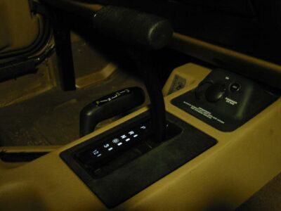
TJ Shifter Installation
Now we get to dig deeper into the interior. Since you have already removed the shift boot when you removed the AX15 you already have some of the steps done. I did not take as many pics of this part of the install. There was some good music on the stereo in my garage that night and I kind of got on a roll 😀
(If you need to remove the T handle from the shifter press the button in and give it a good yank. It will pull out allowing you to install the indicator panel.)
- Remove the entire center console from the Jeep. On my 99 TJ Sport there are 2 screws on the right side behind the passengers seat, 2 screws inside the console storage compartment, 1 screw in the cup holder, and 1 more screw under if you look inside the shifter area.
- Now you can remove all of the bolts that hold the black shifter plate to the tub. The manual one has a round hole in it, the auto one has a rectangular hole.
- Screw down the auto tub plate. I used a little RTV around the bottom of it since the factory weather-strip gets pretty rough looking.
- Bolt the TJ shifter to the plate using the 4 bolts.
- Route the TJ shifter cable in through the firewall and snap the round part of it into the shifter bracket in the big round hole. Then clip the end of the cable to the selector.
- Reinstall the center console.
- Pull off the T handle so you can install the shift indicator panel.
- Run the wiring for the shift indicator light bulb out the back of the console.
- Install the shift indicator over the shifter.
- Push the T handle back onto the shift.
- Snap the XJ shift indicator panel into the center console. (Using the XJ shift indicator is optional. If you use a TJ indicator remember that 1 will actually be 1-2, and that 2 will actually be 3.)
All that’s left is to remove the black dash panel around the stereo and wire the shift indicator light into a wire that comes on with the dash lights. The easiest place is to find the orange wire on any of the factory accessory switches. When you are done it should look like this with the headlights on:
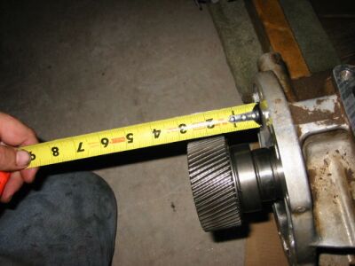
Transfer case input gears
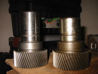
This swap will require you to change the input gear on your transfer case. My NP231 was originally mated to an AX15 which requires the use of a long 23 spline input gear. (I believe that a TJ with the 3 speed auto also uses the long version.) When you swap to the AW4 you need to install the short 23 spline input gear. There is about a half an inch of difference between the two.
You have three options:
- Swap in the XJ 231
- Replace the input gear in your existing transfer case
- Remove your existing long 23 spline input gear and have it cut down by a machine shop. Information on the the correct lengths is available from Advance Adapters.
I chose to replace the input gear with a new one. Bob Bassett chose to cut his down. Any of the above choices will work. It’s really up to you. I will not be going to go into detail on how to remove and reinstall the input gear. This information can be found in the factory service manual. Be sure to have a couple good sets of snap ring pliers handy. You will need them!
***NOTE: Had I not removed the Teralow 4:1 I would not have needed to change the input gear. All of the 23 spline Teralows are of the short variety.
***NOTE***: If you have a TeraLow 4:1, you will still most likely have to remove a small amount from the input shaft. Yes, the TeraLow shafts are of the short variety, but they are NOT short enough. For more info on this, see Stu’s AW-4 swap write-up.
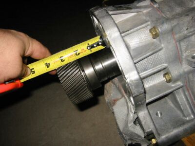
The picture above shows the long 23 spline input gear inserted into the AW4. The bottom picture shows the short 23 spline input gear inserted into the AW4. You can definitely see the difference. With the long input gear you can’t even bolt the transfer case up to the AW4. Installing the short 23 spline input solves that problem.
Transmission Temperature Gauge
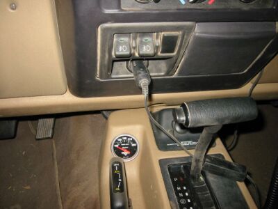
I thought it would be a good idea to install a temperature gauge so I can monitor what is going on with the transmission. I bought an Autometer gauge for around $38.
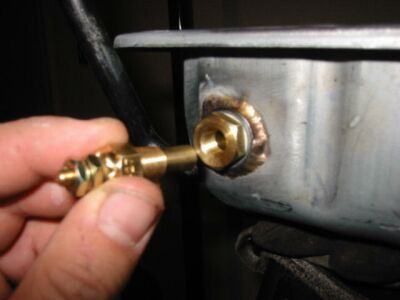
You will also have to drill out the oil pan and weld in a fitting. Here you can see the steel fitting that is welded to the pan. Then the brass fittings from the temperature sensor screw into the pan. Pick your location wisely since clearance is tight. The spot I chose is next to the dipstick tube.
You will need to do some wiring. 1 wire runs from the sensor to the gauge. The rest of wires can be tapped into circuits found under the dash.
TEST DRIVE!!!

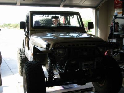
If everything has been installed correctly you should now be able to go on your first test drive. Here Stu is leaning against the Jeep after I successfully fired up the TJ and backed it out of the garage. Stu and I stopped at the first corner and gave each other a high five. All of the hard work has paid off. This is the beginning of a couple of days of road testing. I drove it all over the place and then some. I had nowhere to go but I didn’t care. How sweet it is!
A week later I took it on it’s first trail run. We chose a moderate trail with lots of up and down climbs. I wasn’t ready to go rock crawling quite yet. I wanted to get a better feel for the automatic first. Check out Stu’s write-up on that run. I sure had a lot of fun. I can’t wait to go out again!
THANKS!
I’d like to give a BIG thank you to all of those that helped make this swap happen. Including:
- My wife, Theresa – This woman has a lot of patience. What else can I say? 😀
- Stu Olson – My good friend Stu came over as much as he could and was a big help. I sure do appreciate it!
- Dave at AMC 4×4 Salvage – He gave me a great deal on the XJ and TJ donor parts and provided some very valuable advice. He loaned me a second TCM and TRS so that I could work through the OBD2 issues. Thanks Dave!
- Bob Basset – His write up was the inspiration for this swap. Without his write up I probably would have swapped in an NV4500 instead. We exchanged many e-mails and his help is definitely appreciated!
- Fred Wilson – Fred is from Tucson, AZ. He swapped out his AX-15 for a 3 speed auto a few months prior to my AW4 swap. Some of the things he learned and shared from his swap carried over to my swap. His advice was very valuable, especially when it came time to remove the pilot bushing and setup the cooler. Thanks Fred!
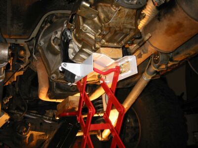
Fabricating the tranny mount plate
I found that neither of the TJ or the XJ tranny mount brackets would work. I decided to fabricate my own plate. I already had a Prothane poly tranny mount that I wanted to keep. There are dozens of ways you could do this. This is how I did mine.
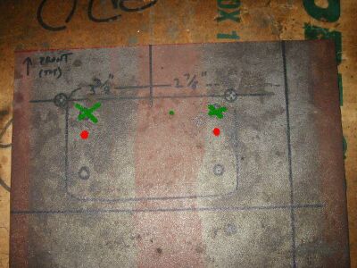
I carefully took measurements with the cross member test fitted to the Jeep. I began with a piece of 1/4″ plate. I then started marking my measurements onto the plate. I decided that the right size would be 6″x10″ for the plate. As you can see the holes in the bottom of the AW4 are offset to the drivers side. Take note of that when you are measuring. Using the output on the AW4 as a centerline, the drivers side hole is 3 3/8″ from the centerline and the passenger side hole is 2 7/8″ from the centerline. Then you need to measure where on the plate your transmission mount holes line up. There are 4 holes in a TJ manual tranny mount. Originally I had marked all 4 holes in the plate and took the picture. In the final product I eliminated the top holes that are crossed out in green and drilled new holes in the mount as shown in red. Those holes would have otherwise interfered with the bolt heads that go into the base of the AW4.
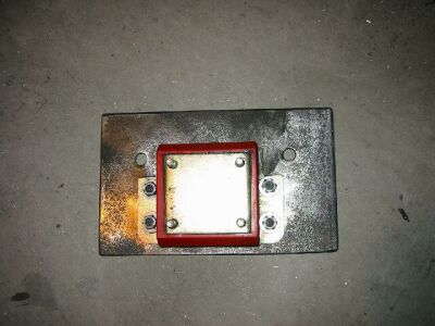
So now we have 6 holes. The two offset holes are used to bolt the plate to the bottom of the AW4. The other 4 holes need to have some studs welded in so that the tranny mount can bolt to the plate. I had some 3/8″ countersunk bolts on my shelf so I decided to use these. They have 5/8″ allen heads. Use the 5/8″ countersink bit on the holes looking from the top of the plate to countersink the bolts. Then drop the bolts in from the top and weld them to the plate. I came back with a grinder and smoothed out the surface. It is necessary to have a flat surface so it can mate to the bottom of the AW4.
The results should look something like this. We are now looking at the mount from the bottom side.
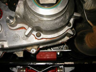
As you can see it is necessary to cut away some of the tranny mount to allow clearance for the bolt heads. This is why I relocated the holes in the above picture. There are two sets of holes in the crossmember. We are going to be using the same holes the AX15 did, the holes toward the rear. Here is a picture of it sitting on the cross member.
Troubleshooting
After your tranny swap, you may encounter a problem. Here are two common problems with things to check to help resolve them.
Engine won’t turn over
- Is the battery hooked up?
- Is the range selector in Park or Neutral?
- Have you adjusted the Park/Neutral Switch?
- Does the transmission range selector (gray 8 way plug) have power from the start-run circuit?
- Does the transmission range selector (gray 8 way plug) have a good ground?
Transmission won’t shift
- Is the TCM plugged in?
- Is the fuse to the TCM good?
- Do you have power to the TCM?
- Is the gray 8 way plug connected?
- Is the black 8 way plug connected?
- Can you try another TCM?
- Download and read the AW4 manual
- Is the problem in the 1-2 range? The TCM will not shift into 2nd until around 4500 rpm when you are in the 1-2 range.
Wirings
First of all if you do this swap I take no responsibility for what happens to the wiring or computers in your Jeep. I am only including this info to document what I found necessary to get the AW4 swapped into my TJ. Please be very careful when doing this part. This is definitely the part that turns most people off from this
I found this to be the most enjoyable part of the swap though. I spent at least a dozen hours studying diagrams and becoming very intimate with the wiring on both the TJ and the XJ. I hope to save some of you a bit of time. This section will be the most detailed part of my write-up.
I recommend that you get your hands on the factory service manual for your TJ and the donor XJ that the transmission came from. In my case that is a 99 TJ and 00 XJ. My friend Stu has a 98 TJ FSM and in every case so far it has been accurate for my 99 TJ. I also subscribed to www.alldatadiy.com for a year. This way I can print out the necessary diagrams from the XJ and TJ. The cost was $40 for both vehicles. Well worth it in my opinion.
Let’s start out with the basics. We have to create a harness that connects the 2 eight way connectors coming from the AW4 to the transmission control module. We then have to tie into a few wires in the TJ harness.
If you are not good with wiring find a friend that is! I did all the research in advance and had everything labeled. From there my good friend Stu Olson comes in to make sure it didn’t turn it all into a big ball of short circuits!
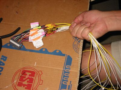
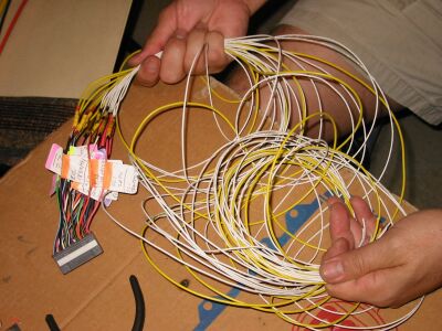
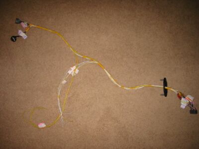
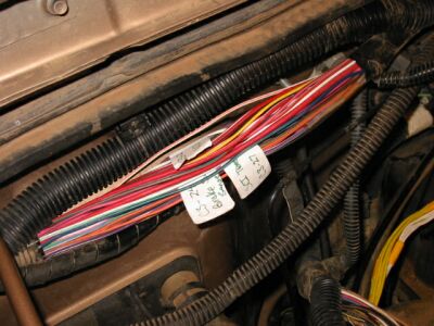
Here is a picture of the harness prior to installing it in the TJ:
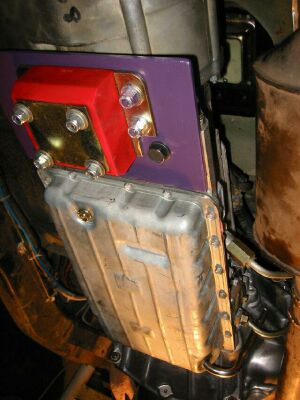
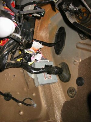
Stu and I decided to install the TCM under the dash on the left side of the vehicle. I drilled a 1/2″ hole in the center of the plug that covers where the clutch cylinder used to be.
Now let’s get on with how we built this.
Wiring diagrams, TRS – Gray 8 way plug
First lets look at the pin diagram of the gray 8 way connector coming from the Transmission Range Sensor.
We have seven wires coming from the TRS. Lets sort them out. The wires coming out of the TRS are different colors than those on the harness side. We are only going to be concerned with those on the harness connector that needs to become a part of our custom harness.
- Pin 1 TRS 1-2 Sense – This is a violet with white stripe wire. It needs to connect to Pin 21 on the TCM plug. (Also known as TRS T42 sense). It’s purpose is to apply 12 volts to pin 21 on the TCM letting the TCM know that the shifter is in the 1-2 range.
- Pin 2 TRS 3 Sense – This is a violet wire. It needs to connect to Pin 9 on the TCM plug. It’s purpose is to apply 12 volts to pin 9 on the TCM telling the TCM that the shifter is in the 3 range.
- Pin 3 Fused Ignition Switch Output (Run-Start) – This is a white wire. When you turn on the key to the run or start mode this sends power to the TRS. The TRS then uses this power to send signals to the TCM indicating what range the shifter is in. This will tie into the wire bundle coming out of the TJ PCM on connector 1 pin A2.
- Pin 4 TRS Overdrive Sense – This is a light green with black stripe wire. It needs to connect to Pin 22 on the TCM plug. It’s purpose is to apply 12 volts to pin 22 on the TCM telling the TCM that the shifter is in the OD range.
- Pin 5 (Not used)
- Pin 6 TRS Reverse Sense – This is a brown with light green stripe wire. It needs to connect to Pin 18 on the TCM plug. It’s purpose is to apply 12 volts to pin 18 on the TCM telling the TCM that the shifter is in the reverse range. (Also known as Back Up Lamp Feed)
- Pin 7 Park/Neutral Position Switch Sense – This is a black with white stripe wire. It’s purpose is to ground the Park/Neutral circuit on the TJ harness when you shift into Park or Neutral so that the starter relay can be engaged which in turn allows the motor to be started. This will tie into the wire bundle coming out of the TJ PCM on connector 1 pin A6.
- Pin 8 Ground – This is the ground necessary to complete the Park/Neutral circuit. It will tie into the wire bundle coming out of the TJ PCM on connector 1 pin 31 or 32.
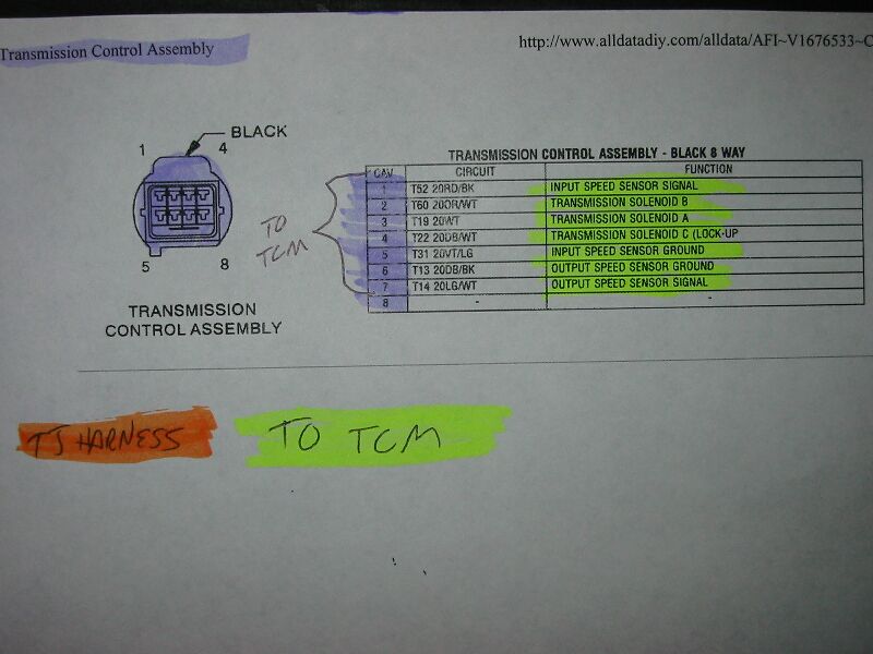
Wiring diagrams, Solenoids – Black 8 way plug
This plug is pretty straight forward. All of the pins on this plug wire to a pin on the TCM plug. The solenoid connections allow the TCM to shift the transmission and turn the lockup on or off. The input and output speed sensors are used by the TCM to calculate the shift points whether they be up or down.
- Pin 1 Input Speed Sensor Signal – This is a red with black stripe wire. It needs to connect to Pin 2 on the TCM plug. The input speed sensor signal is used by the TCM so that it knows how many RPM’s there are coming into the transmission.
- Pin 2 Transmission Solenoid B – This is an orange with white stripe wire. It needs to connect to Pin 13 on the TCM plug. The solenoids are used by the TCM to shift the transmission.
- Pin 3 Transmission Solenoid A – This is a white wire. It needs to connect to Pin 12 on the TCM plug. The solenoids are used by the TCM to shift the transmission.
- Pin 4 Transmission Solenoid C (Lockup) – This is a dark blue with white stripe wire. It needs to connect to Pin 11 on the TCM connector. The TCM uses this solenoid to engage and disengage the lockup.
- Pin 5 Input Speed Sensor Ground – This is a violet with light green stripe. It needs to connect to Pin 1 on the TCM plug. It completes input speed sensor circuit.
- Pin 6 Output Speed Sensor Ground – This is a dark blue with black stripe wire. It needs to connect to Pin 3 on the TCM plug. It completes the output speed sensor circuit.
- Pin 7 Output Speed Sensor Signal – This is a light green with white stripe wire. It needs to connect to Pin 4 on the TCM plug. The output speed sensor signal is used by the TCM so that it knows how many RPM’s there are coming out of the transmission.
- Pin 8 (Not used)
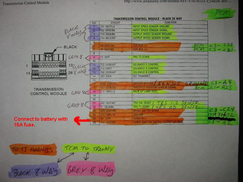
Wiring diagrams, TCM – Black 26 way plug
Now we dig into the connector that plugs directly into the Transmission Control Module. It has 26 pins, some of which go the black or gray 8 way connectors, the TJ harness, and a fused power source from the battery. Lets take a close look at what each pin does and where it needs to go.
- Pin 1 Input Speed Sensor Ground – This is a violet with light green stripe. It needs to connect to Pin 5 on the black 8 way plug. It completes input speed sensor circuit.
- Pin 2 Input Speed Sensor Signal – This is a red with black stripe wire. It needs to connect to Pin 1 on the black 8 way plug. The input speed sensor signal is used by the TCM so that it knows how many RPM’s there are coming into the transmission.
- Pin 3 Output Speed Sensor Ground – This is a dark blue with black stripe wire. It needs to connect to Pin 6 on the black 8 way plug. It completes the output speed sensor circuit.
- Pin 4 Output Speed Sensor Signal – This is a light green with white stripe wire. It needs to connect to Pin 7 on the black 8 way plug. The output speed sensor signal is used by the TCM so that it knows how many RPM’s there are coming out of the transmission.
- Pin 5 (Not used)
- Pin 6 CCD BUS (-) – This is part of the information bus used by the XJ TCM and PCM to share OBD2 information. Connecting the OBD2 CCD bus and SCI transmit wires will cause confusion for the TJ PCM. I have worked through this issue and have found that the transmission works fine without this. I will go into more detail on this later in the write up.
- Pin 7 CCD BUS (+) – This is part of the information bus used by the XJ TCM and PCM to share OBD2 information. Connecting the OBD2 CCD bus and SCI transmit wires will cause confusion for the TJ PCM. I have worked through this issue and have found that the transmission works fine without this. I will go into more detail on this later in the write up.
- Pin 8 (Not used)
- Pin 9 TRS T3 Sense (TRS 3 Sense) – This is a violet wire. It needs to connect to Pin 2 on the gray 8 way plug. It’s purpose is to apply 12 volts to pin 9 on the TCM telling the TCM that the shifter is in the 3 range.
- Pin 10 (Not used)
- Pin 11 Transmission Solenoid C (Lockup) – This is a dark blue with white stripe wire. It needs to connect to Pin 4 on the black 8 way plug. The TCM uses this solenoid to engage and disengage the lockup.
- Pin 12 Transmission Solenoid A – This is a white wire. It needs to connect to Pin 3 on the black 8 way plug. The solenoids are used by the TCM to shift the transmission.
- Pin 13 Transmission Solenoid B – This is an orange with white stripe wire. It needs to connect to Pin 2 on the black 8 way plug. The solenoids are used by the TCM to shift the transmission.
- Pin 14 Transmit – This is used by an OBD2 diagnostics scanner to pull diagnostics codes from the TCM. Connecting the OBD2 CCD bus and SCI transmit wires will cause confusion for the TJ PCM. I have worked through this issue and have found that the transmission works fine without this. I will go into more detail on this later in the write up.
- Pin 15 (Not used)
- Pin 16 Sensor Return (Sensor Ground) – This is a brown with yellow stripe wire. This will tie into the wire bundle coming out of the TJ PCM on connector 1 pin A4. When we pull sensor signals off the TJ harness we need to send to signal ground back to the TJ PCM sensor return. This completes the circuit the TCM needs to get signals from the TJ throttle position sensor and brake switch sense circuits.
- Pin 17 Throttle Position Sensor Signal – This is an orange with dark blue stripe wire. This will tie into the wire bundle coming out of the TJ PCM on connector 1 pin A23. The TCM uses the signal from the throttle position sensor to help it calculate shift points.
- Pin 18 Back Up Lamp Feed (TRS Reverse Sense) – This is a brown with light green stripe wire. It needs to connect to Pin 6 on the gray 8 way plug. It’s purpose is to apply 12 volts to pin 18 on the TCM telling the TCM that the shifter is in the reverse range.
- Pin 19 (Not used)
- Pin 20 (Not used)
- Pin 21 T42 Sense (TRS 1-2 Sense) – This is a violet with white stripe wire. It needs to connect to Pin 1 on the gray 8 way plug. It’s purpose is to apply 12 volts to pin 21 on the TCM letting the TCM know that the shifter is in the 1-2 range.
- Pin 22 TRS T1 Sense (TRS Overdrive Sense) – This is a light green with black stripe wire. It needs to connect to Pin 4 on the gray 8 way plug. It’s purpose is to apply 12 volts to pin 22 on the TCM telling the TCM that the shifter is in the OD range.
- Pin 23 Brake Switch Sense – This is a white with pink stripe wire. This will tie into the wire bundle coming out of the TJ PCM on connector 3 pin C24. This allows the TCM to know when the brakes are being applied.
- Pin 24 Ground – This is a black with tan strip wire. This will tie into the wire bundle coming out of the TJ PCM on connector 1 pin A31 or A32. Provides a ground for the TCM.
- Pin 25 Fused B (+) – This is a pink 20 gauge wire. Rather than tear apart the power distribution center I chose to run this straight to the battery positive terminal. You will want to use an inline 15A fuse. This wire provides constant power for the TCM.
- Pin 26 Fused Ignition Switch Input (Start-Run) – This is a dark blue with white stripe wire. When you turn on the key to the run or start mode this sends power to the TCM. This will tie into the wire bundle coming out of the TJ PCM on connector 1 pin A2.
Wiring – Tying into TJ harness (Part 1)
So now we know what each connector is for and where the wires need to go. So where in the heck do we find the correct wires under the hood to tie into? That’s easy once you’ve read this!
Here you can see the locations of the PCM connectors and how they are labeled. Connector 1 has pins labeled Axx, connector 2 has pins labeled Bxx, and connector 3 has pins labeled Cxx. (We don’t actually tie into any wires that run from connector 2.)
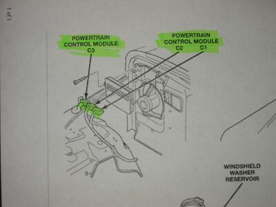
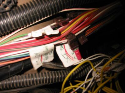
I recommend disconnecting the plugs from the PCM and then following them back to the center of the firewall. Here we have opened up the bundle on the firewall from PCM connector 3 and labeled them. You will only need to identify the brake switch sense wire. (I do not recommend connecting the CCD bus or SCI transmit wires. Read more on this later in the article.)
- Brake switch sense – This is a white with pink striped wire. We need to connect pin 23 on the TCM plug to this wire. Carefully find the wire and label it. Stu and I stuck a needle into the wire and then checked it with an ohm meter. Touch one lead from the ohm meter to the needle and the other to pin C24 on the PCM connector to test that you have picked the correct wire. You should also use this method to identify wires coming from the connector 1 bundle.
Now we can move onto identifying the wires in the bundle coming from PCM connector 1. Once again we need to refer back to the chart to identify the correct wire color. Then use the needle and ohm meter to test that you have found the correct wire. Here are the wires that need to be labeled in this bundle:
- Fused Ignition Switch Output (Start-Run) – This is a dark blue wire. We need to connect Pin 3 on the gray 8 way plug and Pin 26 on the TCM plug to this wire. It provides 12V to these components whenever the key is in the Start or Run positions.
- Sensor Ground (Sensor Return) – This is a brown with yellow stripe wire. We need to connect Pin 16 on the TCM plug to this wire. It completes the sensor circuits. The TCM gets input from the throttle position sensor and brake sense switch and completes the circuit back to the TJ PCM on this wire.
- Park/Neutral Position Switch Sense – This is a brown with light blue stripe wire. We need to connect Pin 7 on the gray 8 way connector to this wire. Whenever the shifter is in the Park or Neutral position this circuit is completed allowing the starter relay to be engaged by the turning the key.
- Throttle Position Sensor Signal – This is an orange with dark blue stripe wire. We need to connect Pin 17 on the TCM plug to this wire. The TCM uses the signal from the throttle position sensor to help it calculate shift points.
- Ground – There are two ground wires coming from the PCM. They are both black with tan stripe. We need to connect Pin 24 from the TCM to either one of these.
Now that we have identified all of the correct wires lets see what it takes to tie it all together!
Wiring – Tying into TJ harness (Part 2)
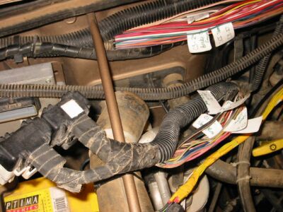
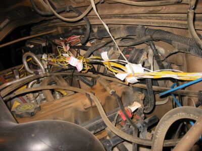
Here we see the location of the AW4 gray and black 8 way connectors. After the transmission is installed run these up the firewall on the passenger side of the motor. This is where they will connect to the harness you have been making.
Here is the temporary state that the TCM is suspended in. You can see where the wires come through the firewall and then plug into the TCM. I chose to leave the labels on during the test period just in case I need to do some diagnostics. Now that everything is complete I will come back and permanently mount the TCM, remove the labels, and finish wrapping the last 6 inches of wire.
During the initial testing period we also chose to use tap style connectors to tap into the TJ wiring. Now that everything is working correctly we will solder some pigtails into the TJ harness that will end at some Molex connectors. Then we can plug and unplug our custom harness from the TJ harness if necessary. Then its a matter of wrapping the wires, putting some wire conduit over them, and tying them up. When complete it will look as neat as the factory wiring.
Like I said before, this is only temporary!!!
That completes the temporary wiring portion of the swap. Let’s move on to getting this thing installed!
Wiring – Pics of Stu making the harness
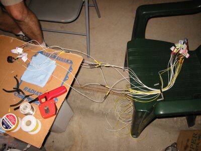
I had labeled all of the wires coming out of the plugs a couple days before and color coded them according to where they needed to go. It was now a matter of soldering in some wires to create the harness. This is where Stu Olson’s expertise comes in handy. Here is a photo gallery of the man hard at work!
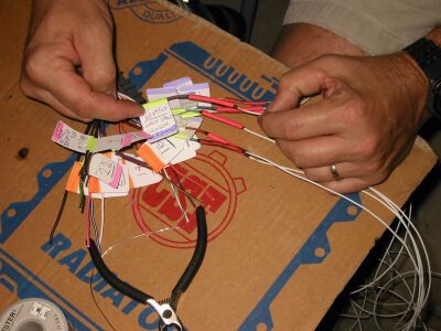

Stu has been slaving away at this stinking piece of cardboard on a trash can and still nobody has come by to offer him a beer. (Boy, is he underpaid!!!)