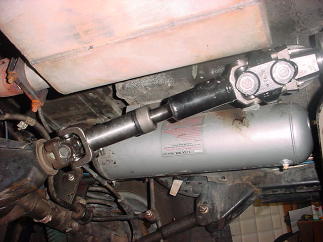
These are instructions for replacing the output shaft on a np231 transfer case and installing a Slip Yoke Eliminator. This is intended as a guide line only. During the installs we used two different kits an Advanced Adapters and Bayou Geep kit. The two kits are similar but, the minor differences are important to each kit. So make sure your read the instructions that came with your kit to insure that the work is done correctly.
You need Adjustable rear control arms to adjust the pinion angle after you are done. We got enough adjustment out of the lower arms to set the angle, some Jeeps may need adjustable upper arms as well. Also, you may need rear shock re-locator brackets. Another option to the re-locator brackets is flipping the shocks so the canister in up, you will need to check with your shock manufacture to see if this may be an option for you. One other thing that can be done regarding this is, to cut away part of the rear lower spring perch allowing the shocks full travel without hitting. This is your call, what ever works in your situation.
Some things you might want to consider changing while doing this install are the transfer case chain and the o-ring that is between the transfer case pump and the pick up tube. I would highly recommend you getting an o-ring replacement. The transfer case chain would probably be a good thing to replace if you have over 50,000 miles on the chain you have in your vehicle and you don’t plan on taking the transfer case part soon.
Some Tools/Supplies needed include: 8mm socket/wrench, 1-1/8″ Socket, Impact Wrench, Snap Ring pliers, 10mm 12pt socket, 15mm socket, 10mm Allan wrench, 19mm socket, 13mm socket, 1/2″ wrench, Locktite (we used red “High Strength”), RTV silicone, 3″ extension, pry bars, ratchet, 2 quarts ATF.
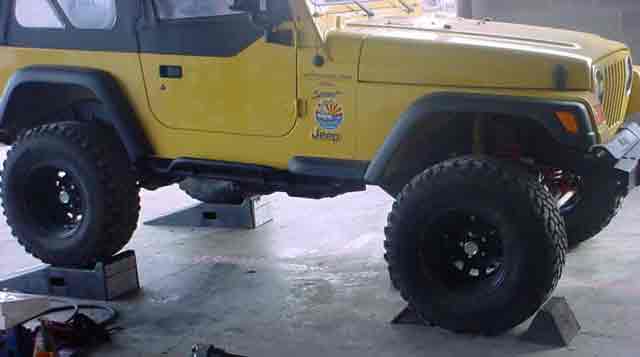
We used ramps. The ramps will allow most installers to sit under the vehicle while you are doing the install. The ramps are not necessary but, do provide some convenience. With the vehicle up on the ramps and the front wheels chalked, we can get started.
Put the transfer case in 4 Lo. Next you will need to block the transmission up. You need only to hold it in place because you will be removing the cross member/transmission skid plate. Remove the cross member/transmission skid plate, you will need to remove the 4 nuts on the transmission mount as well as the 6 bolts holding the skid plate to the frame.
You can now drain the transfer case. There is a drain and a fill plug that are 10mm allan heads. While the transfer case is draining remove both front and rear drive shafts. To remove the rear shaft remove the 4 – 8mm bolts on the axle yoke, the front can be removed by first removing the 4 – 8mm bolts in the axle yoke and then the 4 – 8mm bolts on the transfer case yoke. Now remove the 1-1/8″ nut in the center of the front transfer case yoke, this will allow this yoke to be removed. The yoke should just slide off, you can take it off and set it aside.
This part may differ from vehicle-to-vehicle. You will need to remove anything off the tail shaft of the transfer case. On my 1999 TJ there was an oil slinger/dust protector. It wasn’t easy to remove, but can be removed by prying between the case all the way around and “walking” it off the output shaft. The 2001 TJ had a balancer. The balancer can be removed with 3 – 6mm 1.0 thread pitch bolts x 2″ long, I believe fine thread. Turn the bolts in by hand and then torque them a couple of turns each working around until the balancer comes off. Next remove the seal behind from the case.
You need to remove the speedometer gear and tuck it behind/out-of-the-way of the transfer case. There is one bolt that holds this in via a fork, then pull the gear/assembly out, be careful not to damage the o-ring around this. You might want to remember the orientation of this assembly. If it is not put back the same way as it was removed the speedometer will not work. This problem can be fixed if it occurs by rotating the speedometer gear back to it’s original position, then disconnecting and reconnecting the battery to reset the vehicle’s computer.
Remove the snap ring on the rear output shaft, leave the snap ring that hold in the bearing.
Remove the 5 bolts that hold the rear output case to the rear cover. Then pry the output case off the rear cover, be careful not to brake anything.
Remove the snap ring that hold the fluid pump in place, it is on the output shaft.
Remove the bolts holding on the rear cover. There is one at the top of the cover that you will need a 12 point 10mm socket for the rest will take a 15mm socket. For reassembly, remember the black bolts go in the sleeved holes (at 10 & 4 o’clock). Once you get these bolts removed you will need to pry off the rear cover the fluid pump will come off with the cover, there are pry spots between the cover and the case near the sleeved holes. Be mindful of the spring that is on the shifter rod, you can leave it in place remove it for the time being (just make sure to put it back in place before reinstalling the rear cover).
Once you get the rear cover off you can remove the shafts. Remove the front and rear shafts and chain all at the same time, this is one place it helps to have someone working with you. The rear output shaft will slide out of the shifter fork assembly.
Now you have the rear output shaft removed there is a snap ring that holds on the chain gear, remove this snap ring then the main gear and next the syncro gear.
You are ready to reassemble everything. You need to clean off the rear cover and the main case mating surfaces and the rear cover to tail case mating surface on the rear cover. You might need to clean off all the bolts also.
This is one place where there is a difference in the kits/installations. The Bayou Geep shaft came with 2 needle bearing assemblies that need to be pressed or tapped into place in the syncro gear. The Advanced Adapters kit does not have this, instead the syncro gear rides directly in the rear output shaft. In any case you should pre-lube the contact surfaces with assembly grease or a few drops of ATF before reassembling.
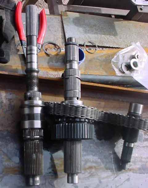
In the picture you can see the stock output shaft and the replacement side-by-side. If you are so astute to notice, disregard the snap ring that is on the upper part of the replacement shaft, a lesson I learned.
Now slide the syncro gear on the shaft and then the main gear. The Bayou Geep kit also included a thrust washer you need to slide on after the main gear. You can now place the snap ring on the shaft that holds everything in place. and you are ready to re-install the shafts into the case. Slide the shafts into the case with the chain between them as one unit, you will have to twist the rear output shaft so that it lines up with the shifting fork assembly.
RTV the mating surface of the case and place the rear cover on, remembering to replace the spring on the shifting shaft if you removed it. Also make sure the pump is connected to the pickup tube. Start installing the bolts, there are brackets that hold wires on the upper corners on the case bolts. Remember the 10mm 12 point bolt goes in the top and the black bolts with the washers go in the holes with the sleeves. Torque the bolts to specs (25-30ft lbs).
Place the snap ring on the shaft that holds the pump in place and install the speedometer gear on the output shaft.
Note: The Bayou Geep kit’s speedometer gear has smooth ends on it, one side is longer than the other. Place the long end towards the transfer case. The Advanced Adapters the speedometer gear is continuous and the kit has another snap ring to put in place after the speedometer gear, the Bayou Geep’s kit doesn’t.
RTV the tail housing case and install it on the cover. You will need to mate the housing with the fluid pump, so a bit a wiggling may be in order. Install the bolts that retain the tail housing and torque to specs.
Replace the speedometer assembly, put the retaining fork in place and install the bolt.
Place rubber washers, that came with the kit, over the output shafts (front & rear) and install the yokes on both (torque to specs).
Install the drain plug in the rear cover and fill the transfer case with fluid, then tighten fill plug.
Install the front drive shaft and then replace transmission skid plate/cross member.
You can measure for your new rear driveshaft and order it.
I have not mentioned in this where to use the Locktite. The places to use the Locktite should be obvious when you look at the bolts and nuts you are working with. All of them get it.
When you install the drive shaft you will need to set your pinion angle such that the pinion points straight up the drive shaft.
I hope this helps your install go smoothly and if there is anything that was inadvertently left out I apologize.