After installing the AW4 auto transmission in my TJ, it was time to seriously consider a transmission skid. With the manual tranny, this was never much of a concern since it had no tranny pan bolted to its bottom side. While smacking the tranny body onto a rock is never a good thing, the chances of it surviving such a mishap is much better than the fluid pan on an auto tranny. And so, I started poking around the TJ forums and vendor web sites looking for a suitable skid plate.
It became evident that my existing engine oil pan skid would be up for retirement once this project was finished. The new tranny skid would extend forward from the tranny and protect the oil pan as well. Since the new tranny skid would be bolted to the vehicle’s transfer case skid, the front of the tranny skid would also have to be mounted to the frame. Mounting it to the engine/tranny (like the existing oil pan skid) would transmit a lot of drive train vibrations to the frame. I have enough of those already, on account of the poly tranny and motor mounts, and I don’t need any more.
Mounting the rear edge of the tranny skid to the transfer case skid won’t be too difficult. Mounting the front edge, by the oil pan, to the frame would present more of a challenge. Back to the web to do some more information surfing. It seems that for the folks on the East coast, the Skid Row engine skid seems to be quite popular. As I looked through the Skid Row, I found a page with some replacement parts on it.
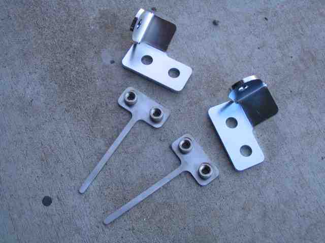
The Skid Row engine skid mounting brackets were just what I was looking for. They are a little pricey, but since this was a build it yourself project, I decided to splurge a bit and get a pair of brackets and two nut plates. I’ll save some money on other stuff (like labor) so the $70 to mount the front end of the skid was acceptable.
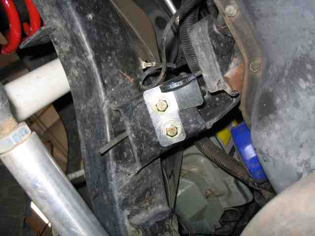
Here is a pic of the Skid Row bracket bolted into position on the passenger side motor mount. It fit nice and tight on the bottom side of the mount. Since it is quite a trick to get nuts onto the bolts, you can see why I opted to get the nut plates too.
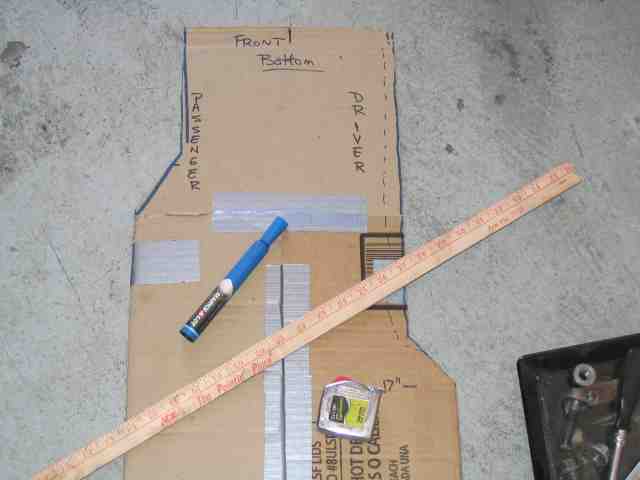
With the front mounting brackets taken care of, it was time to work up a template. I grabbed some cardboard from the garage and with the help of some racing tape, a suitable sheet of template material was produced.
I gave my buddy Robert a call and asked if he could shoot me some measurements of his skid. Robert runs the same Alumi-flex suspension that I do. His very capable ’98 TJ also runs an automatic tranny. So….it made sense to me to get some numbers to use as a starting point. For what it is worth, passing skid measurements back and forth through e-mail isn’t the best way to duplicate another guy’s skid plate. After Robert saw a photo of mine, the first thing he mentioned was that it didn’t look like his. Go figure!
Before I got too serious about finalizing the template, we used a forklift and picked up a couple of corners of the TJ while checking for clearance up front. I didn’t see any problems with what I had and so decided to go with it. If I find otherwise after I get on the trail, I’ll have to make an adjustment as necessary.
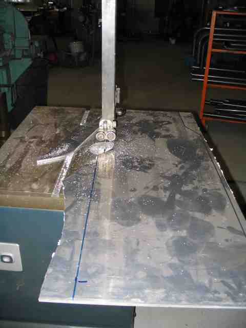
With the template’s shape transferred to the aluminum, I used Troy’s band saw to cut the 6061 1/4″ aluminum plate. Don’t ask me what this piece of 1/4″ alloy costs…..it came from Troy’s parts and pieces pile. It was the remnant of a 4’x8′ sheet that cost several hundred dollars. Did I mention that aluminum corner guards and side sliders are not cheap? I wish I had the $$ to put them on my TJ. Talk about a weight savings.
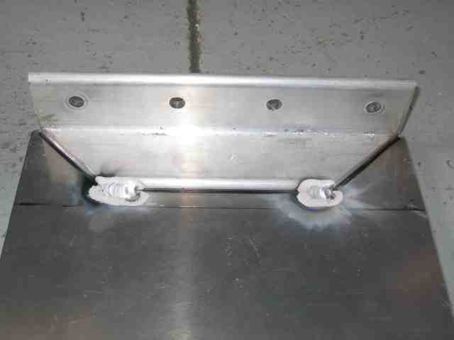
I used 1″ square tube for the arms that connect the brackets to the front of the skid. One end of each arm is attached to a bracket that is bolted to the motor mount. The other end of the each arm is welded to an 1/8″ thick metal plate which bolts to the front of the engine skid. Troy welded the plate to the arms after I positioned them and tightened the bolts (to prevent their movement). Grade 8 hardware is used throughout the installation.
Engine & Tranny Skid
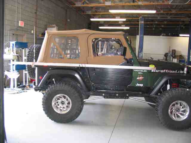 So how do you carry your aluminum angle stock on your TJ? You bungee cord it to your side sliders. Besides keeping your sheet metal out of the rocks, they do a great job of hauling small amounts of metal around town.
It was time to stop by South West Steel to pick up some 2″x2″ angle aluminum in the 6061-T6 variety. I can tell you how much this stuff costs…..$3.41 a foot. I bought 10′ for this project and have about 18″ left over….enough to make an extra brace or replace a piece if I had cut it wrong. (assuming it was not a big mistake)
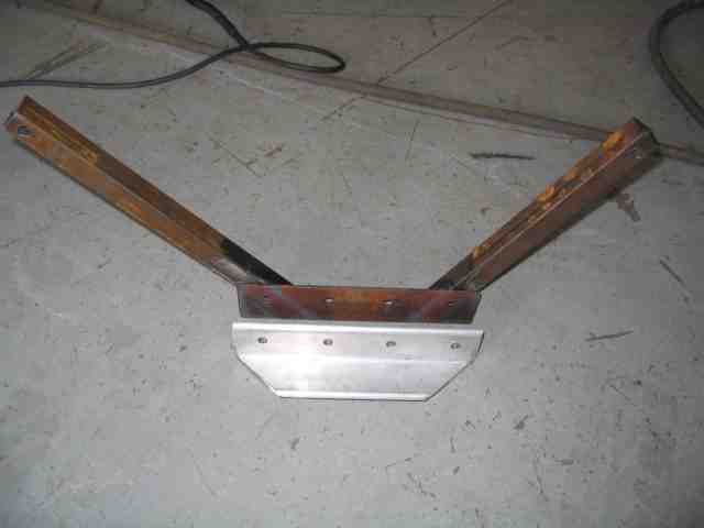 I remembered to snap a better picture of front bracket and the angle aluminum it attaches to. When I get done with the cutting, grinding, and fitting, I’ll get it powder coated.
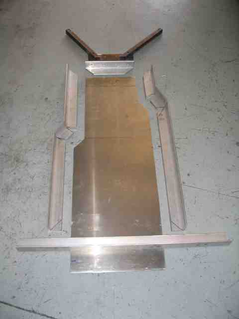 Here is the whole mess of stuff prior to being assembled. You can get an idea of how it is suppose to look (note, it may not look anything like this by the time I deem the project completed). The plan is to TIG weld the angle aluminum to the skid plate….making a 3″ long bead every three or four inches. In this photo, the skid plate has not been cut for its final length. Once I have the angle aluminum attached at the front of the skid, I’ll measure for final length and trim the skid plate before welding the sides and rear section into position.
 With the front end of the skid taken care of, the angle aluminum was tacked onto the skid plate in a couple of places so I could hang the front of the skid from the bracket. I needed to get an accurate measurement for the overall length of the skid.
 I decided to attach the new tranny skid to the front edge of the existing t-case skid which went in when my Alumi-flex lift was installed. I drill and then tapped five holes in the skid for 5/16″ bolts. The plan was to drill five matching holes in another piece of angle aluminum which would be welded to the rear edge of the new skid plate.
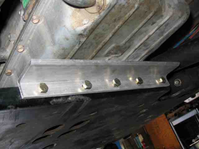 Grade 8 hardware will hold the angle aluminum to the edge of the t-case skid. The Jeep gods were smiling on me as I managed to NOT break a drill bit or the tap when I did the holes. I found that one of the bits I had in my index was quite dull. Ever try one of those Drill Doctor sharpening machines? I hadn’t used one before but after doing a couple of mine with it, I was totally impressed at the new edge it put on the drill bit. Donna is always asking me what I want for a birthday present….I think I just came up with an idea. Thanks Troy for letting me put an edge back on a couple of my drill bits.
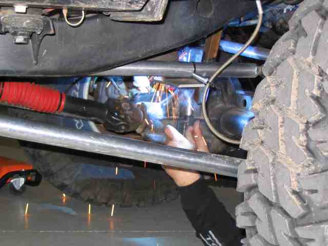
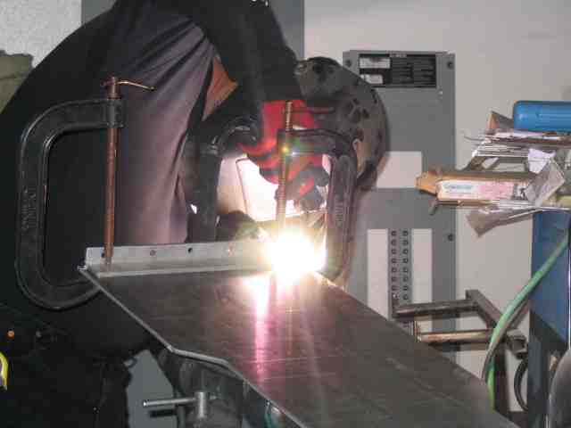 With the rear bracket drilled and cut, Troy TIGs the bracket to the skid plate. I was unaware of just how much heat gets pumped into the welding process on aluminum. The alloy sucks up the heat very quickly and with this being 1/4″ material, welding two pieces of it together makes the welding machine grunt.
Engine & Tranny Skid
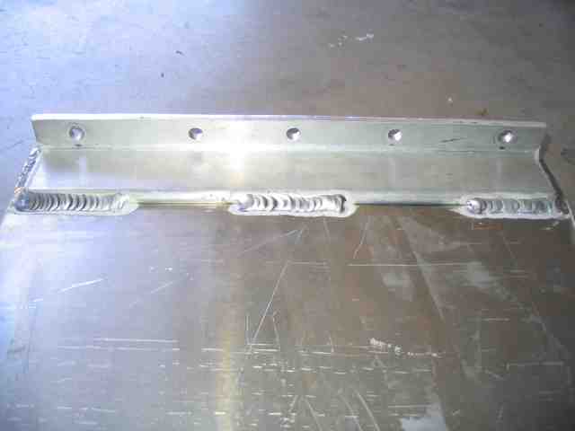 Troy finished the welding, attaching the 2″ angle aluminum to the skid plate. As was already done to the piece in the above photo, some of the angle aluminum will have to be trimmed for clearance purposes.
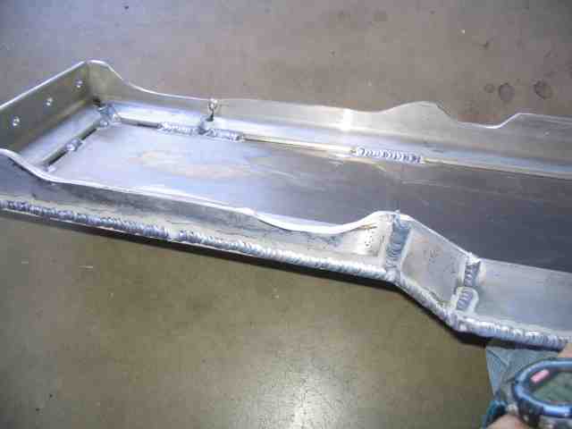
 Here is the final layout (at least until I decided to change it) of the skid plate. The outer seam where the angle and skid plate join are welded all the way around the outer edge. On the inside, Troy stitched it here and there as appropriate.
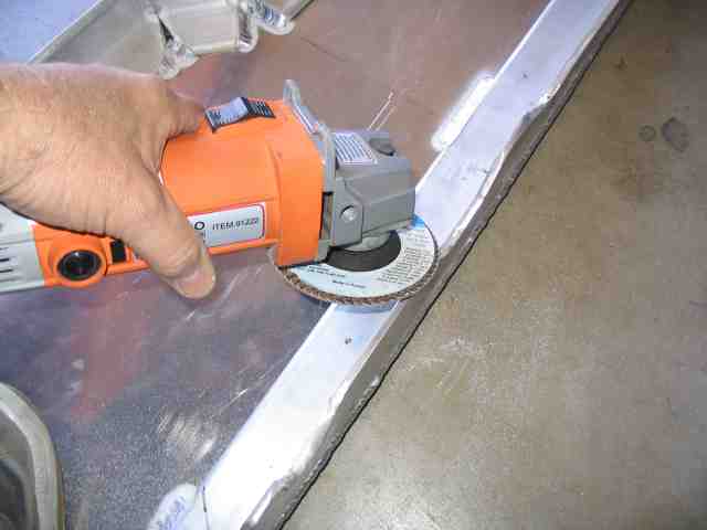 Using an angle grinder and some coarse flapper discs, I started the process of making the skid fit around all of those things that can get in the way (namely, the exhaust system in my case). I used a coarse cutting blade in my jigsaw when the section to remove was a bit more than I wanted to do with the grinder.
 The clearancing took a little longer than I expected, mostly due to the many test fits that were required. I didn’t wish to remove more than was necessary and as the fit improved, I found a few other spots and needed some minor trimming. I would have hate to pay a shop to have this done…..some extra bucks in labor for this step would have driven up the bill.
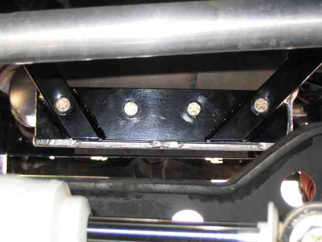 Hey….check out the powder coating! That rusty old bracket was ran through the media blaster and then hung in the powder coating oven with a bunch of other items. Turned out very nice…..much better than my sanding and rattle can flat black would have done. This is the front of the skid, looking towards the rear of the vehicle (over the front axle).
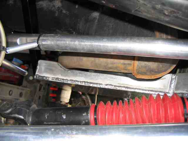 Looking in from the driver’s side….what looks like the shadow of the exhaust pipe (on the aluminum) is actually the trimmed away aluminum. I may or may not have to trim a bit more. I’ll find that out once I get things flexed up a bit and get the motor to torque a bit as well.
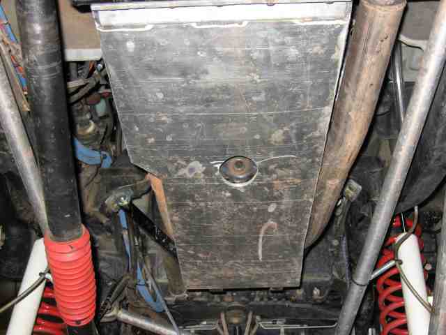
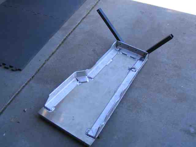
 I apologize for this one getting kind of crooked. Trying to shoot this one with the camera laying almost flat on the ground was a little difficult. But you get the idea of what it looks like all bolted into position.
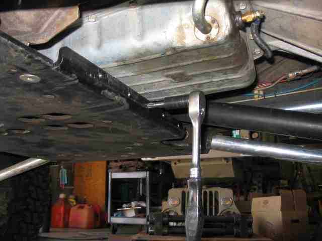
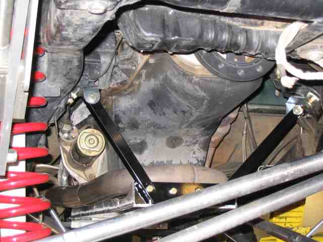 I had the TJ on the lift and was almost able to get a full shot of the front of the skid (and brackets) without the drag link and track bar in the way…..like I said, almost. But this gives you a pretty good idea of what it looks like. I weighed the skid on the bathroom scale and it showed 14 pounds. Troy had commented to me, while welding it, that he thought it was getting a bit heavy. Perhaps so but I am very happy with the weight and extremely satisfied with how it all turned out. A big thanks to Troy for handling the TIG welding. One of my friends has been watching the progress of the skid and was wondering if I was going to cut an oil drain hole. At this point, it is pretty easy to take on and off. I only do 3 oil changes per year (less than 10K miles per year) and so the extra 10 minutes I spend taking it off and putting it back on isn’t going to add up to that much time in the grand scheme of things. If it becomes a hassle, I can cut a hole. that is about it for now. If I make any changes, I’ll do an update to this write-up.
Good trails to you and remember to TREADLightly!
Update: 05/26/2006
Lady has made a few trips over the rocks since this skid was installed. Last weekend, I ran Die Hard, a solid 5.0 trail here in the Phoenix area. I am happy to report that this skid performed very well. At one point, I had the weight of the vehicle parked on the skid. I had high centered the front end….both tires were just barely scratching the dirt. While scraped up, there were no dents in the aluminum. Those 1/2″ thick reinforced edges did a good job of distributing the rock impacts.
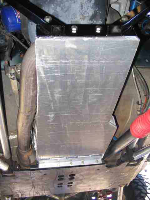
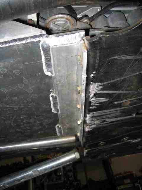 A few folks expressed a concern with the method I chose for connecting the engine skid to the center skid. I didn’t shear any of the grade 8 hardware. Likewise, I didn’t mangle or peal the 1/4″ aluminum that was bolted to the steel center skid. You can see fresh rock rash right at the leading edge of the center skid…..just a little knick in the aluminum that is about 1/8″ up and away from the steel edge. I’m sure you can find a rock that will hit that aluminum….but after dragging Lady across Die Hard for more than six hours, I’m very confident this skid will do everything I ask of it. If you like the idea of an aluminum skid, check out my recently installed aluminum gas tank skid. Half the weight of the steel skid it replaced and after its initiation on Die Hard, every bit as good from what I can determine.
Update 12/27/2006:
I finally got around to taking a photo of the oil drain hole (yes, I added one) on the skid plate. Even though I only change my oil 3 times a year (only put 9K miles on each year), I got tired of taking the skid off when it was oil change time.