York OBA TJ Installation
by Dave Gallegos (TJBoomer on JU
There comes day in your life when one decides that a stock Jeep just isn’t enough. We need bigger tires which lead to higher lifts. Higher lifts mean more components to make our Jeeps work like a fine watch on steroids.
Then you notice the other Jeepers bent over (you assume they are praying to the tire gods) at the trail head. You find out lower tire pressure means better traction on the rocks and those guys are airing down. At the trails end, those same Jeepers are airing their tires back up. How cool is that? We then decide we just gotta have compressed air too. If for nothing else, it’s just too cool to pass up. It’s a Jeep thing… we do understand.
There are several different products and configurations to choose from on the market today…Quick air, Co2 tanks and, the most favored by far for serious Jeepers is the York compressor. This is the route I took, but is the most expensive and time consuming of all the choices and requires a lot of patience.
These York compressors are tough and can take quit a beating. They can provide a never-ending source of air for filling tires, running air tools, seating a tire bead, and can bring that unforgettable smile to the face of a child when you air up their water wings. What a feeling of accomplishment.
So… where to get started. First, this project takes a lot of planning research, and design. Think about where you want to position all the components. Kilby Enterprises web site contains a plethora of information to include installation of their kits, schematics, diagrams, York service manuals, links, lotsa parts and kits. The York Compressor Service Manuals can be downloaded in PDF (Acrobat Reader) here.
In order to make this project as simple as possible, I broke the system down into four basic components/modules; the compressor, air tank, oil removal filter (optional)/check valve and air manifold. I wanted my system to be modular so that it would be easy to tear down for maintenance and repair purposes. This meant that each basic component would be connected with quick connects (QC’s). I decided I didn’t want to drill or cut my Jeep in any way if at all possible.
After weeks of research on the Internet, which included many visitations to www.stu‑offroad.com for technical information to move the air box to make room for the York compressor and Brad Kilby’s site for the links to other’s who had done this project, I finally decided to start the project by gathering the parts.
I started by procuring a used TJ air box and tube. I didn’t really want to cut mine, in case the project never came to fruition. After weeks of searching the net, I located a used air box, air tube, and to my surprise, not just one, but two junkyard York compressors (1-210 and 1-206) included with the Kilby KE-1000 compressor bracket kit and clutch on Jeeps Unlimited “FOR SALE” forum. The air box and the tube from one person was $20 + shipping. The 2 – Yorks, bracket kit and clutch were $150 from another (thanks David). I also understand that these items can be found on Ebay.
REQUIRED TOOLS |
|
| Drill/Drill bits – assorted sizes | Assorted Standard/metric combination wrenches |
| Air impact w/ sockets 22mm or 7/8″ | Measuring tape |
| Assorted Metric and Standard sockets | Rivet gun w/rivets (if bolts are not used) |
| Large adjustable/crescent wrench | Circuit tester/mulit-meter |
| 1/4″ NPT Tap – Requires 7/16″ drill bit | Small mechanics telescoping magnet |
| Rubber Mallet | Pliers |
| Wire stripper/cutter/crimper | Round rat tail file |
| Assorted flat head/phillips screw drivers | Electrical tape |
| Hack saw/miter power saw | Masking tape |
| Hammer | All weather tape |
| Right angle square | Black Sensor Safe RTV |
| Spreader wrench for York clutch assembly | Anti-sieze |
| Torque wrench | Teflon pipe tape |
| Dremel w/small cutoff wheel and drum sander | |
ADDITIONAL TOOLS/SUPPLIES REQUIRED IF FABRICATING BRACKETS |
|
| Welder | 1 – 4′ x 1″ x 1/8″ Strap metal |
| Assorted files | 1 – 4′ x 1″ x 1/4″ Strap metal |
| Angle grinder | 1 – 4′ x 1/2″ x 1/4″ Strap metal |
| Vise | Metal scriber or medium tipped marker |
|
PARTS AND SOURCES |
||||
| Qty. | Item | Part # | Source | Price |
| 1 | York Compressor with 4 bolts | 210 | Salvage Yard | $20-$70 |
| 1 | York v-belt 6″ clutch | should come w/ compressor | Salvage Yard | $0 new = $90 |
| 1 | Air Manifold 5-1 Air Manifold |
KE-AM6 159133 |
Kilby Enterprises Northerntool.com |
$35 $14.99 |
| 1 | York Bracket Adapter Kit | KE-1000 | Kilby Enterprises | $125 |
| 20′ | Insta-Grip Air Hose | 3/8IG | Kilby Enterprises | $20 |
| 1 pr. | Flange Fittings Tube-O Roto-Lock Fittings |
28723 44760 |
Kilby Enterprises | $25 |
| 1 | Pressure Switch | PSW3 | Kilby Enterprises | $30 |
| 1 | 0 – 160 psi Pressure Gage | GA2MB | Kilby Enterprises | $10 |
| 1 | One Way Check Valve | DB38 | Ebay Kilby Enterprises |
$5 $15 |
| 1 | Intake Filter | FS-07-050 | Kilby Enterprises | $20 |
| 1 | Oil Removal Filter | Coi26C3-S | Kilby Enterprises | $65 |
| 1 | Oil Return Line | COI-OILRETURN | Kilby Enterprises | $20 |
| 1 | Adjustable Relief Valve | NC25 | Kilby Enterprises | $5 |
| 1 | York Dip Stick (optional) | 90616 | Kilby Enterprises | $5 |
| 1 | Lighted SPST (single pole single throw) switch | 27411 | Overtons.com | $12 |
| 20′ | Automotive 16 Gauge Wire 15′ Red – 5′ Black |
Autoparts Store | ||
| 1 | Male/Female Bullet Connector | Personal stash | ||
| 2 | | Wire Tap Connectors | Personal stash | ||
| 1 | Male Spade Connectors | Personal stash | ||
| 9 | Female Spade Connectors | Personal stash | ||
| 1 | 5/16″ Round Terminal End | Personal stash | ||
| 1 | Spray Paint Can Lid From Premium Rust-Oleum Can |
Personal stash Walmart |
$0 $3.79 |
|
| 1 qt. | 10W-30 oil | Walmart | $1.35 | |
| 4 | 1/2″ 10-24 Bolts, Nuts and Lock Washers |
hardware store | $1.50 | |
| 2 | 1-1/4″ 10-24 Allen Bolts W/Lock Washers and Nuts |
$2.50 | ||
| 1 | 2″ Rubber Pipe Coupler | $1.80 | ||
| 2 | 3″ Hose Clamps | Salvage Yard | $1.00 | |
| 1 | Quick Connect Rubber Cover | Tractor Parts Store | $2.30 | |
| 2 | 3/8″ – 1/4″ NPT Reducer | Autoparts Store | $1.40 | |
| 12 | 1/2″ NPT – 3/8″ NPT Reducer | Autoparts Store | $3.50 | |
| 3 | 3/8″ NPT Male Hose Connectors | Autoparts Store | $4.00 | |
| 4 | 1/4″ NPT Female Hose Connectors | ` | Autoparts Store | $5.20 |
| 2 | 90 Degree 1/4″ NPT Male/Male | Autoparts Store | $4.00 | |
| 1 | Male Hex Nipple | Autoparts Store | $1.30 | |
| 1 | 3/8″ NPT Plug | Autoparts Store | $.70 | |
| 1 | 1/4″ NPT Plug | Autoparts Store | $.50 | |
| 1 | 1/4″ NPT Drain Valve | Autoparts Store | $1.25 | |
| 4 | 1/4″ NPT Female Quick Connect Couplers | Autoparts Store | $11.20 | |
| 2 | 1/4″ NPT Male Quick Connector Couplers | Autoparts Store | $5.60 | |
| 6 | 3/8″ – 1/4″ NPT Male Barb Hose Connectors | 272-0604 | Kilby Enterprises | $4.80 |
* Shipping not included in above prices.
This list is by no means all inclusive. Each person will use different techniques requiring different parts. Adjustments to this list and instructions may be required to fit your particular needs. For example the air manifold; there are two choices on the list of “Parts and Sources”. Your choice will change the required connectors and manifold mounting procedures to complete the OBA install. If I’ve missed anything or something is incorrect within the instructions, please feel free to let me know by sending an email to: [email protected] Any and all help would be greatly appreciated and would insure these instructions are as up to date as possible for all who would benefit from them.
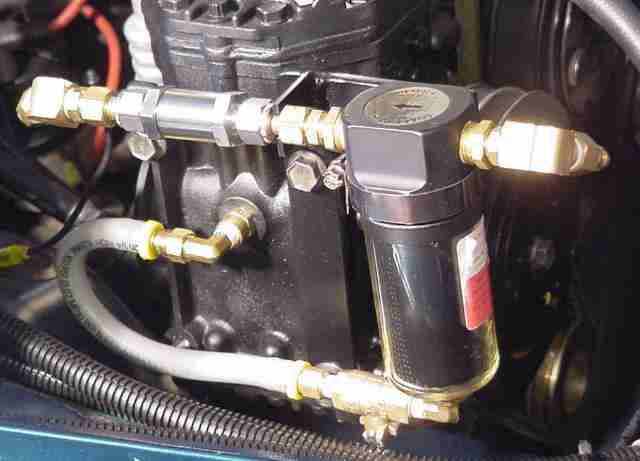
Figure 9
- Loosen the inside bolt at the forward end of the fuse/relay (PDC) box. See Figure 10.
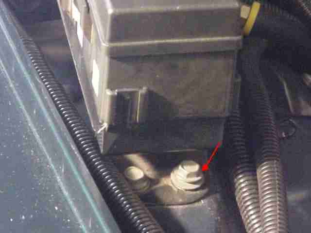
Figure 10
- Install the air manifold module and tighten the bolt that holds the fuse/relay (PDC) box to the fender. See Figure 11.
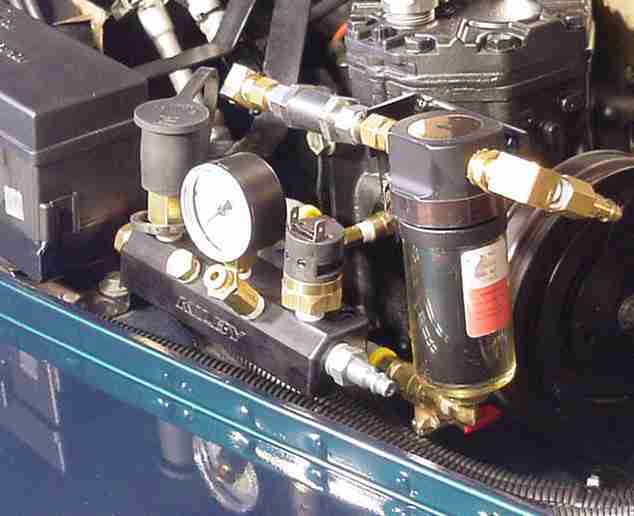
Figure 11
- Create and connect a black wire with a female spade connector at one end and a female bullet connector at the other end to go from the pressure switch to the compressor clutch magnet wire.
19. Create and connect a red wire with a female spade connector at each end to go from the last relay pole 30/51 (refer to Figure 9 above for relay wire connections) to the pressure switch. See Figures 12 and 13.
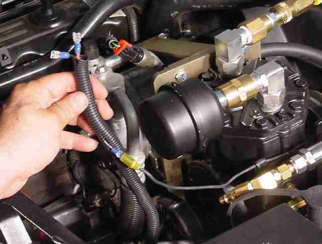
Figure 12
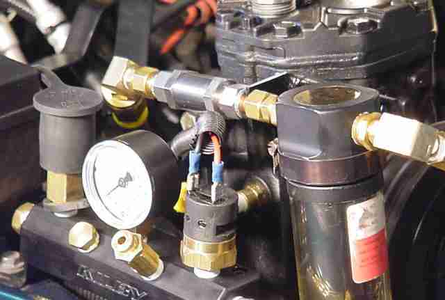
Figure 13
Turn the ignition key and the compressor switch on and check the operation of the compressor clutch. Aaaaahhhh… the power of a click. What? No click? If no click is heard you will need to check the relay ground wire for proper grounding. I had this problem and it took just a few minutes to fix. Got a click? Alright!
Okay… lets get this baby hooked up.
- With 2 – 1/4″ NPT male barb hose connectors, 2 – 1/4″ NPT female quick connectors, Teflon pipe tape and (according Kilby Enterprises) at least 3′ of hose, create an air hose to go from the compressor output to the oil removal filter input. Check for leaks and install. See Figure 14.
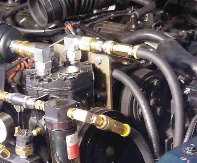
Figure 14
- With 2 – 1/4″ NPT male barb hose connectors, a 1/4″ NPT female connector, a 1/4″ NPT female quick connector and Teflon pipe tape create an air hose to go from the check valve output connection to the front bumper/air tank. Check for leaks and install.
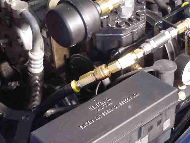
Figure 15
- With 2 – 1/4″ NPT male barb hose connectors, a 1/4″ NPT female connector, 1/4″ NPT female quick connect and Teflon pipe tape, create an air hose to go from the front bumper/air tank to the air manifold module input. Check for leaks and install.
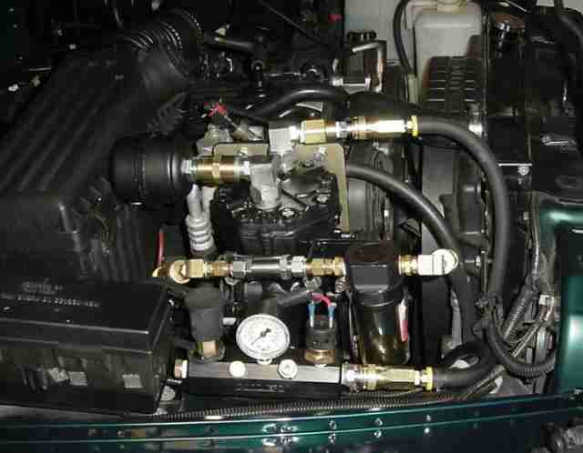
Figure 16
23. Dress all hoses to insure they don’t come in contact with sharp edges or moving parts.
Project almost completed. This was the time I started getting all tingly and had to slow down to insure the job was completed properly. It was now time to check and recheck all bolts and connections. Every thing check good? Time to start the engine, test the system and make final adjustments to the pressure switch and safety valve in accordance with the supplied respective instructions. I was lucky and the system worked like a champ on the first try. I was a happy camper.
Last thing to do was apply all weather tape to the connectors on the bumper to keep out dirt and water, stand back and enjoy the new OBA feature my Jeep no sported. Job well done…
Well, I hope this write-up is a benefit and inspiration to others. I tried to write this article in such a way that it would be easy to follow and understand even for the not so mechanically inclined. Hopefully it will inspire those who have wanted to add OBA to their vehicle and never got around to it due mainly in part to the idea that it would be to difficult. Even for me it was a very intimidating project to take on, so as I went through the process of writing this piece I tried to add some of the pitfalls that one might encounter as well as some added tips.
Many thanks go out to my wife (Terri) for her help, never ending patience and understanding in this endeavor to accomplish something I thought I could never do. She was a world of encouragement. Thanks Babe.
Also, I would like to thank Brad and Robert of Kilby Enterprises for such a great product and for all of their support and technical advice as well as their overwhelming patience with all my not so bright questions. They were instrumental in the completion of the project and provided the website with all required information to complete the job. My hat is off to Brad and Robert for their undying patience and infinite wisdom.
Last but not least, a great deal of gratitude goes to Stu Olson for hosting this write-up so that it would be available to all who care to read and benefit from it. Thanks also Stu, for providing a website to all that contains a wealth of information that has become a standard to be measured by. Keep on Wheelin…
If there are any problems and you would like to ask questions or would like to contribute tips or advice, please feel free to email (Link – [email protected]) me… Any and all suggestions (good or Bad) would be greatly appreciated.
Resources:
Air Box Relocation – Daless2’s info on the relocation the air box
York Compressors – Manuals and technical Information
Northern Tools – a pretty good source of on-line tools and parts
Kilby Enterprises – OBA Technical Information and Links
Kilby Enterprises
1847 N. Keystone St.
Burbank, CA 91504
Phone: 818-848-2900
Fax: 818-848-2974
[email protected]
York OBA TJ Installation
MODIFYING THE AIR BOX AND TUBE FOR RELOCATION
Franks write-up on Stu’s Website provided all the technical info I needed to complete this change. Some minor modifications were incorporated into his instructions since I didn’t have a snorkel and didn’t want to drill any holes. That meant a fabricated bracket would be necessary to make it look as stock as possible.
AIR BOX BOTTOM HALF
You can follow the above instructions for air box relocation and adjust accordingly or if you want to fab your own bracket then follow these instructions:
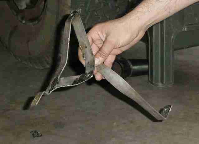
The bracket was fabricated from 1″ x 1/8″ strap metal. This bracket will form a triangle to go from each of the three mounting holes on the bottom of the air box. See diagram.
1. Remove the air box and tube from the Jeep, then remove the air horn from the bottom half. You won’t need this anymore.
2. Remove the mounting fasteners from the bottom of the air box.
3. Turn the bottom half over so that the mounting fastener holes are up.
4. With a hacksaw and metal scriber, mark and cut a length of strap metal approximately 9 1/2″ long. Just slightly longer than the two fasteners furthest from each other.
5. With hammer and vise, bend the strap metal at each end to fit flat over the two holes and contour along the bottom of the bottom half.
6. Mark with a center punch and drill the two end holes with a 5/16″ drill bit.
7. Attach this piece, that we will now refer to as piece “A”, to the air box bottom as it would normally be attached to the fender using the stock bolts and nuts. See Figure 1.
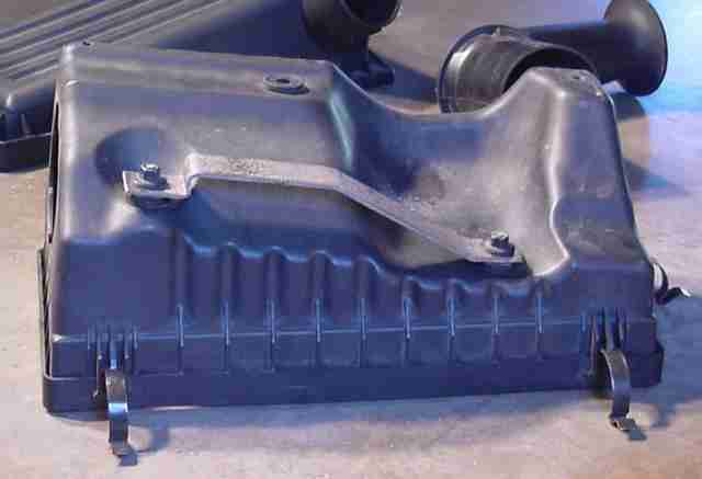
Figure 1
8. With a hacksaw and metal scriber mark and cut another length of strap metal just slightly longer than required to go from the third bottom mounting hole to a position near one of the bolted holes of piece “A” this second piece will be referred to as piece “B”.
9. Mark and drill a hole at one end of piece “B” with a 1/4 width=”25%” drill bit.
10. With hammer and vise, bend the strap metal as required at each end to insure piece “B” sits flush on the third hole and slightly overlaps piece “A” near the selected hole of piece “A”.
11. Attach piece “B” to the third mounting hole and adjust piece “B” till an angle can be scribed where pieces “A” and “B” intersect.
12. With a hacksaw, cut this angle on piece “B”.
13. Reinstall piece “B” on the air box bottom and adjust to proper position against piece “A” and tack weld pieces “A” and “B” at their intersection. See Figure 2.
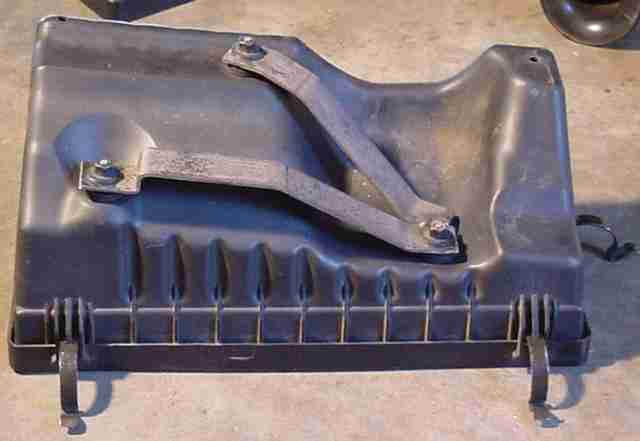
Figure 2
14. With a hacksaw and metal scriber, mark and cut a third piece of strap metal (a little longer than required) to complete the bracket triangle between pieces “A” and “B”. This is piece “C”
15. With a hammer and vise, bend piece “C” as required at each end to follow the contour of the air box bottom to complete the triangle.
16. With the metal scriber, scribe the required angles to cut to complete the triangle on piece “C”.
17. With a hacksaw, cut the angles scribed on piece “C”.
18. Tack weld piece “C” between pieces “A” and “B” to complete the triangle.
19. Once all pieces are tack welded together, remove the bracket and finish welding all three pieces together.
20. Angle grind and file to desired perfection. See Figures 3 and 4.
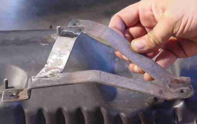
Figure 3
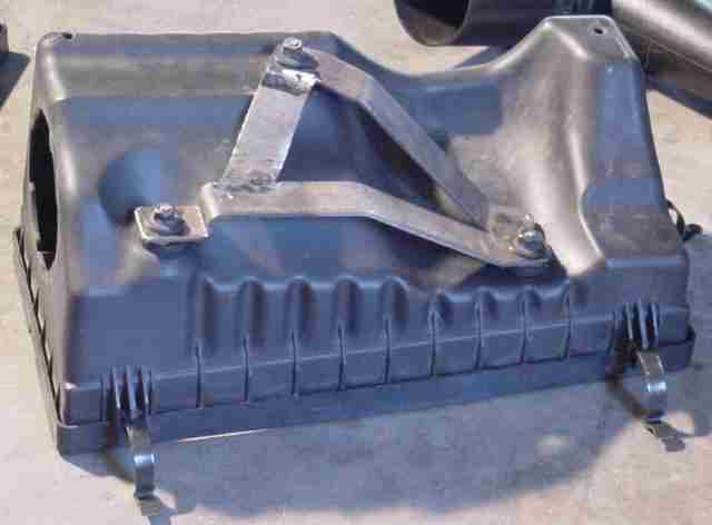
Figure 4
Completing the bracket requires a brace that can utilize the passenger side motor mount to frame bolt. Again, 1″x 1/8″ strap metal is used to make this piece to weld to the bracket we just fabricated above.
1. With a hacksaw and metal scriber, mark and cut a length of strap metal approximately 12 1/2″ long. This length is actual longer than required and will be cut to the proper length later.
2. Drill a 7/16″ hole approximately 1/2″ from the end.
3. Scribe another position approximately 1-1/2″ from this same end.
4. Bend the strap metal 90 degrees on this mark. See Figure 5.
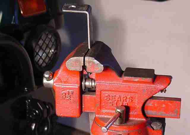
Figure 5
5. Half way up this piece, using an adjustable/crescent wrench and a vise, twist the strap metal approximately 120 degrees. See Figure 6.
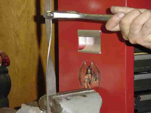
Figure 6
6. Cut a length of 1/2″ x 1/8″ strap to approximately 9″ long with a hacksaw.
7. Using an adjustable/crescent wrench, twist this piece of strap metal approximately 90 degrees. See Figure 7.
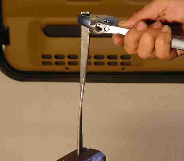
Figure 7
8. With a hacksaw, cut a 1-1/2″ x 1″ x 1/8″ triangular fillet brace. See Figure 8.
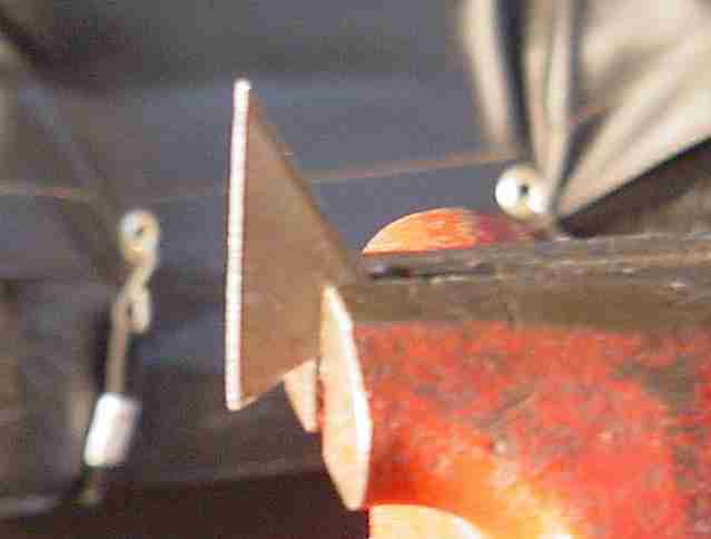
Figure 8
9. Trial fit the 1″ x 12-1/2″ piece by removing the passenger side motor mount to frame bolt and temporarily mount this piece into position.
A second set of hands would come in really handy, so call a friend. My wife was available and was invaluable in these next few steps.
10. Position the air box bottom bracket into approximate position, and with a medium point marker, mark the desired height and angle to be cut. My long brace ended up being 9-3/4″ long as measured from the 90 degree “L” bend to center of the angle just marked. See Figure 9.
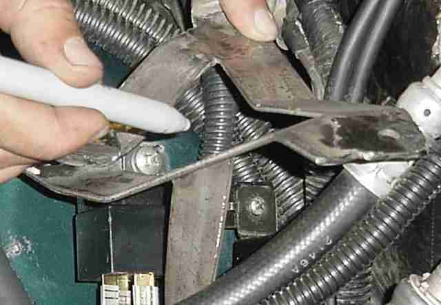
Figure 9
11. Remove the long brace from the motor mount to frame bolt.
12. With a hacksaw, cut the long brace at the previously marked angle.
13. Tack weld the air box bottom bracket into position on the long brace with two tack welds. See Figure 10.

Figure 10
14. Temporarily install the entire bracket into position and temporarily install the air box.
Make any and all final necessary adjustments to the brace. Insure hood clearance is checked by putting a drop light in the engine compartment, passing the cord to the floor underneath the vehicle and plugging the light in underneath the vehicle. Turn on the light and slowly close the hood while watching for clearance between the hood and air box. Once all adjustments are complete, it’s time to strengthen and complete the bracket.
15. Finish welding the brace to the air box bottom bracket.
16. Tack weld the 9″ x 1/2″ x 1/8″ strap metal to strengthen the brace as seen in Figure 11.
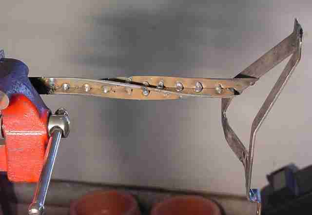
Figure 11
No fair laughing at the welds in these pictures. This was my wife’s first attempt at welding by herself (she tried so hard). Actually they’re not too bad for her first try. Wouldn’t you say?
17. Weld the 1-1/2″ x 1″ x 1/8″ triangular brace fillet next to the bolt hole to increase the strength of the 90 degree bend. See Figure 12.
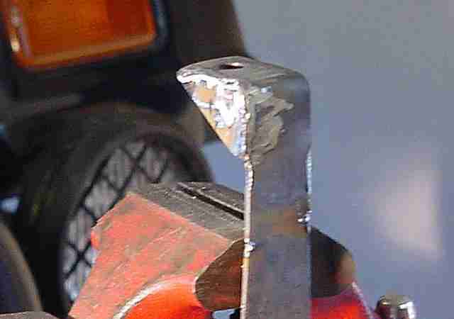
Figure 12
18. Grind, file and thoroughly clean to desired perfection. Rattle can spray paint the entire bracket and allow to dry. See Figure 13.
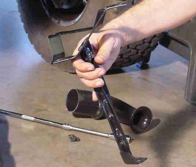
Figure 13
York OBA TJ Installation
AIR BOX UPPER LID
Now that the air box bottom half is in position and the air box is installed, it’s time to work on the air box lid. Franks write-up for air box relocation contains the required information for completing the project and fabricating the tube to required specs for proper fit. Just like earlier, I’ve made a few minor changes to the instructions and I used a different method to plug the air box lid outlet.
Required items for this portion of the project are a 2-3/4″ OD ABS flange or equivalent (of all the parts for this project this was the most difficult to locate – it took weeks to find), 4 – 10-24 bolts with nuts and washers, Black Sensor Safe RTV silicone, and a rattle can spray paint lid from a can of Premium Rust-Oleum spray paint (this seemed to fit the air box lid outlet the best).
1. Insert the spray paint can lid into the air box outlet and, with the RTV silicone, seal the lip of the paint can lid on the inside of the outlet and allow to dry. See Figure 1.
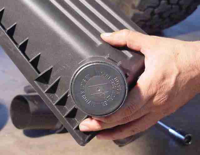
Figure 1
2. There are three ribs that need to be removed on the large end of the air box lid. A Dremel with a cutoff wheel will make quick work of this. See Figure 2.

Figure 2
3. Trial fit the 2-3/4″ OD flange to the air box lid where the ribs were removed and make adjustments for proper fit.
4. Drill four holes on the corners of the flange with the proper size bit for the 1/2″ x 10-24 bolts and four matching holes into the air box lid.
5. Temporarily install the flange and 4 each 1/2″ x 10-24 bolts with washers and nuts. See Figure 3.
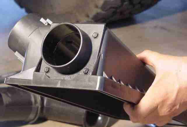
Figure 3
6. With a medium point marker, mark the lid where a whole needs to be cut for the flange.
7. Remove the flange and bolts and cut a large enough hole in the center of the marked circle large enough to fit a Dremel drum sander.
8. With a Dremel rotary tool and Dremel drum sander, increase the size of the hole to required diameter. A hole saw can be used for this step, also. I didn’t have one and didn’t want to purchase one. How you accomplish this step is your call.
9. Clean the edges of the enlarged hole really good with a round rat tail file. Don’t want any plastic pieces getting into the throttle body and clogging things up during engine operation.
10. Apply a thin layer of sensor sensitive Black RTV silicone to both the flange and the mating surface of the air box lid.
11. Install the 2-3/4″ flange utilizing the 4 bolts with nuts and washers and allow to dry. See Figure 4.
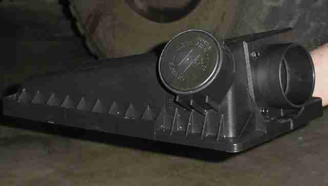
Figure 4
12. Install this newly modified air box with air filter into position. See Figure 5.
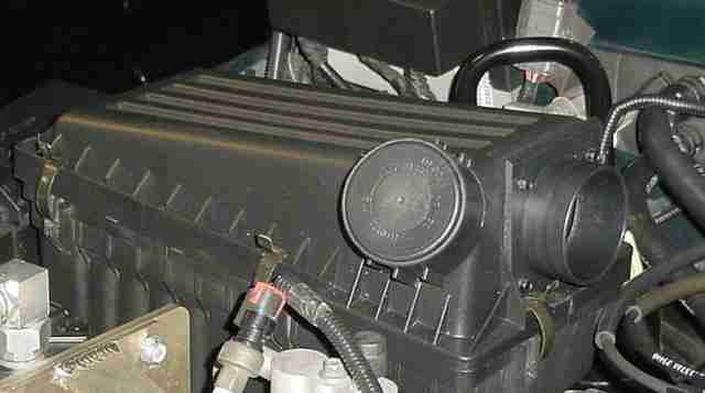
Figure 5
York OBA TJ Installation
THROTTLE BODY TO AIR BOX TUBE
Here again, Franks write-up for air box relocation provided the required information with only a few minor changes. Required items for this portion of the project include the 2″ rubber pipe coupling and 2 – 3″ hose clamps.
1. From the center of the PCV hose nipple, measure 2-1/4″ toward the bellowed end and mark accordingly. Measure at least two more times to insure it is correct.
2. Cut the air tube at this location with either a hacksaw or miter saw. Cut as straight as possible.
3. Clean all frayed plastic from the edges of this cut on the tube half with the nipple.
4. Take the tube half with the bellows and measure 7-1/2″, from the cut you just made, toward the bellows and mark accordingly. Again measure at least twice.
5. Cut the tube on this mark as straight as possible using the hacksaw or miter saw.
6. Clean all frayed plastic from the edges of this cut on the tube half with the bellows.
This is what you should have at this point. See Figure 1.
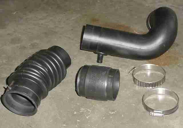
Figure 1
Now to reconnect the two halves. Franks write-up utilizes a 2-1/8″ ID stainless steal exhaust pipe as an inner sleeve, some minor reshaping of the tube is required and 2 – 4″ hose clamps. See Frank’s write-up for more details on this method.
To connect the two halves, I used a 2″ rubber pipe coupler from Home Depot and 2 – 3″ hose clamps from the salvage yard. However, all of these parts can be purchased from Home Depot/Lowe’s to secure the two ends together.
6. Firmly push the 2″ rubber pipe coupler into position (lubrication may be needed to assist) with the two 3″ pipe clamps and leave the hose clamps loose. See Figure 2.
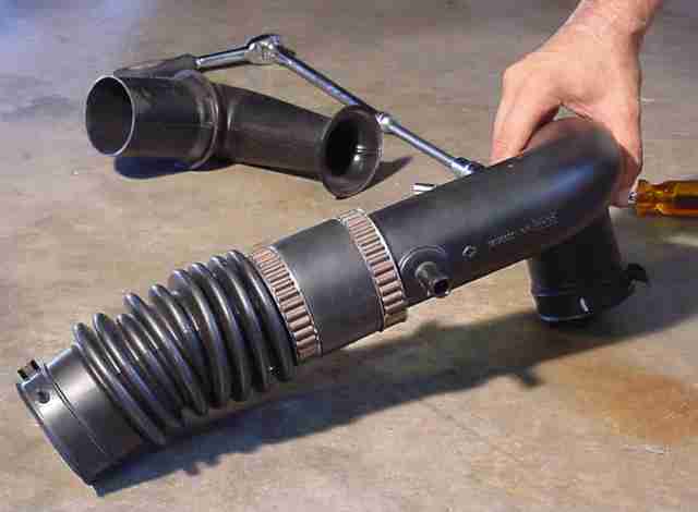
Figure 2
7. Trial fit and make the required adjustments to the connected tubes prior to tightening the hose clamps. See Figure 3.
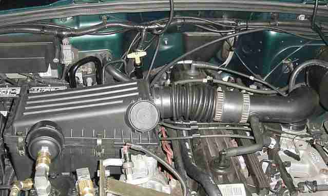
Figure 3
8. Optional finishing touch – Clean and wipe down the air box pieces with Armour All for that professional look.
Grab the nearest cold beverage, sit back and enjoy/admire a project well done. Good job.
York OBA TJ Installation
YORK COMPRESSOR PREPARATION
With my various other projects, installing an On-Board Air system in my Jeep had been one of the most satisfying yet most frustrating projects I’d ever taken on. There were many unscheduled trips to the hardware store to purchase a needed part or to return/exchange a part for the correct one. My wife was instrumental in this area, willing to make the run on a moments notice. Hopefully, this write-up will alleviate most of the frustrations I encountered. Now would also be a good time to download the York Compressor Service Manual from this link: http://www.ccicompressor.com/. It is in PDF Acrobat Reader Format so you will also need to download and install this no cost software from http://www.adobe.com.
After weeks of searching for a salvage yard York compressor (I live in a very small town), one was finally located on the “For Sale” forum of JeepsUnlimited and was purchased from one Mr. Trappet who had decided not to install an On-Board Air system on his Jeep. I was very fortunate (Thanks Dave) because not only was there one York compressor included in the package, but 2 compressors (a 210 and a 206 for parts) and a Kilby KE-1000 bracket kit (bracket, pulley, belt and hardware).
With the deal finalized and the package in the mail, it was time to organize and start getting things together. First stop, I called Kilby Enterprises and ordered an air manifold (can also be purchased from Harbor Freight Tools), Flange/Roto Lock (depending on the York head type) fittings, oil removal filter (optional if you want to filter the oil and return it to the York compressor), 0-160 PSI pressure gauge, adjustable relief valve, pressure switch, intake filter, assorted hose barb connectors and Insta-Grip Goodyear high temp/300 PSI air hose.
Parts I scrounged from other sources include a one-way check valve and a pressure regulator from Ebay (Kilby Enterprises also sells this check valve and pressure regulator). The regulator was purchased for when ARB Lockers are installed and has not been installed as of yet. A rubber Quick Connect cover and 1/4″ NPT tap were located at the local John Deere tractor implementation parts store and all other parts (i.e. tape, nuts, bolts, 1/4″ NPT fittings…) were all locally purchased from Home Depot/Lowe’s and auto part stores. The lighted on/off switch was obtained off the internet from Overtons.com.
Time to start preparing all the parts for installation after they arrive and all required parts were purchased. (WOW…what a jigsaw puzzle.)
1. With the double V belt clutch pulley installed on the York compressor, attach a negative ground jumper cable from a 12 volt battery (negative side) to the body case of your compressor. Then attach a positive jumper cable from your battery positive pole to the wire lead of the clutch pulley. You should hear the clutch engage with an audible “click”. Hear the click? If so, the clutch is good. Great! If not, then one needs to be purchased. Now spin the clutch pulley and listen/feel the two top ports. One port (discharge) should be pumping air out and the other port (suction) should be sucking air in. Does it work? Great! Compressor and clutch pulley work. We are on a roll. If possible, do this check at the salvage yard prior to paying for it.
2. I removed the clutch pulley and magnet from the compressor and, using masking tape, covered the two ports and shaft/shaft bearing seal and took the compressor to my nearest bead blaster for a thorough cleaning. I then painted the compressor with some Wal-Mart Rust-Oleum semi-gloss black rattle can spray paint and allowed it to dry over night.
3. Once the painted compressor was totally dry, all the masking tape was removed. The flange fittings that came on the compressor are also removed at this time and the new Flange fittings with gaskets or the Tube-O Roto Lock fittings with “O” rings are installed using 10W-30 oil to coat the gaskets or the “O” rings. The Flange fittings can be tightened down to spec (17 – 25 ft-lb), while the Roto Locks are just finger tight at this time.
4. Remove both oil fill plugs (one on each side) and completely drain all of the old oil and refill with 12 fl-oz of new 10W-30 oil. Replace the oil plugs. Also at this time, I made my own dip stick for checking the oil level from the instructions provided by Kilby Enterprises web sight. See Figure 1.
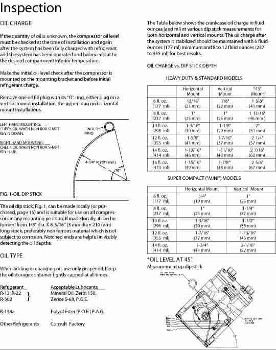
Figure 1
5. Apply some Teflon pipe tape to the threads of the discharge flange fitting and install the 1/2″ NPT – 3/8″ NPT reducer. Now apply Teflon pipe tape to the threads of the 3/8″ NPT male connector and install the male connector into the 1/2″NPT – 3/8″ NPT reducer. See Figure 2.
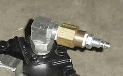
Figure 2
6. Apply some Teflon pipe tape to the suction flange and install the female/female 1/2″ NPT fitting to the suction flange. Apply Teflon pipe tape to the compressor air filter and install it into the 1/2″ NPT fitting. See Figure 3.
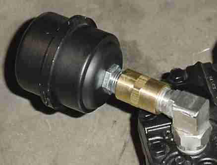
Figure 3
7. This step is optional if you did or did not purchase the Oil Removal Filter Kit. If the Filter kit was purchased, then now would be the time to install the 90 degree elbow provided in the kit with Teflon pipe tape applied to the threads into the compressor oil filler hole. See Figure 4.
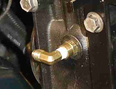
Figure 4
8. Re-install the clutch magnet and clutch pulley with a spreader wrench, socket and ratchet. See Figure 5.
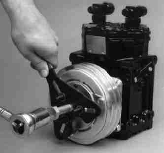
Figure 5
Take note of the key location and apply a red or yellow mark on the clutch pulley to show the key location. This mark can be utilized to check the oil level per the York Compressor Manual. The Key must be oriented a certain way to properly check oil level.
Finish tightening the flange fittings and the compressor is now finished. See Figure 6.
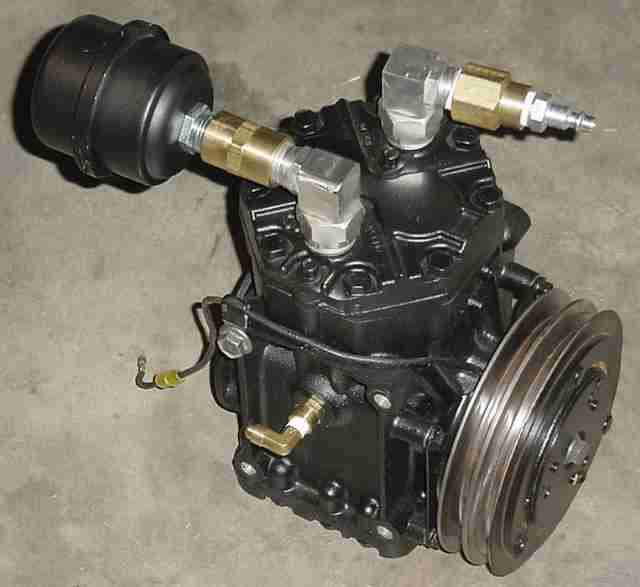
Figure 6
Set the compressor aside, admire your handy work and let’s begin creating the other two modules. You will need assorted standard combination wrenches, Teflon tape and brass fittings.
York OBA TJ Installation
OIL REMOVAL FILTER MODULE (OPTIONAL)
The second module will consist of the oil removal filter, check valve and mounting bracket. The required items for this part of the project will be the Oil Removal Filter, 2 – 3/8″ NPT – 1/4″ NPT reducers, a 90 degree male/male 1/4″ NPT elbow, a 1/4″ NPT female connectors, a 3/8″ NPT – 3/8″ NPT male hex nipple, a one way check valve, a 1/4″ NPT male connector, Teflon tape and assorted wrenches. (If the oil removal filter is not utilized then the check valve can be attached directly to the third (air manifold) module using a 3/8″ NPT – 3/8″ NPT male hex nipple, a 3/8″ NPT male connector and some Teflon tape once the third module is complete. There will then be only 2 modules; the compressor and the manifold and you won’t need the bracket mentioned above.)
Assembly of the second module (oil removal filter and check valve):
1. With Teflon tape applied to the threads, take note of the arrow on top of the filter, and install a 3/8″ NPT – 1/4″ NPT reducer to the “in” side of the filter.
2. Apply Teflon tape to the threads of a 90 degree male/male 1/4″ NPT elbow and attach this to the 3/8″ NPT – 1/4″ NPT reducer that was just installed on the filter.
3. Apply Teflon tape to the other end of the 90 degree elbow and install a 1/4″ NPT female connector.
With this side completed, it should look something like this: See Figure 7.
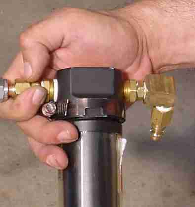
Figure 7
4. Now, apply Teflon tape to the 3/8″ NPT – 3/8″ NPT male hex nipple and install it into the “out” side of the filter.
5. Apply Teflon tape to the other end of the hex nipple just installed and install the check valve taking note of the air flow direction.
6. Apply Teflon tape to a 3/8″ NPT – 1/4″ NPT reducer and install the reducer into the check valve.
7. With Teflon tape, install a 1/4″ NPT male connector. This side of the oil removal filter should look similar to this. See Figure 8.
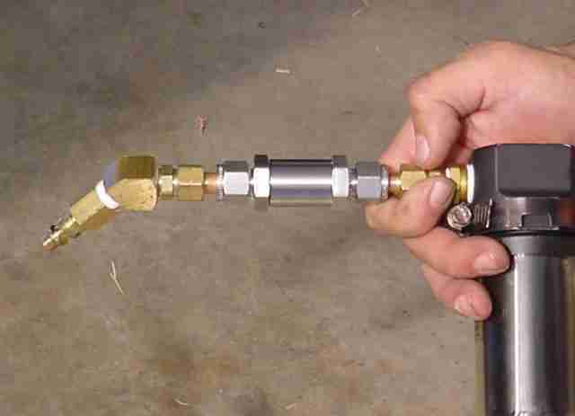
Figure 8
After completing the above directions, you should pressurize this oil removal filter and check valve with compressed air and check for leaks by inserting this module into a bucket of water. Tighten any connections as required. No Leaks? Great! Now it’s time to connect the oil return line to the oil removal filter. Follow the instructions provided in the kit. See Figure 9.
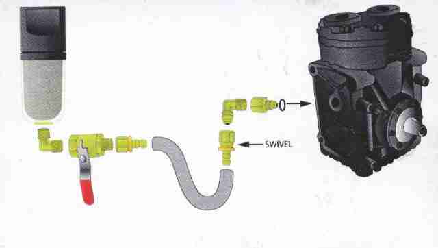
Figure 9
8. Cut the required length of provided hose (I used approximately 10″of hose since my oil removal filter was located right on the compressor; the length would depend on where you decided to place yours so measure carefully before cutting) and install the two barbed female fittings by firmly pushing them onto the hose. See Figure 10.
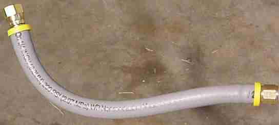
Figure 10
9. Remove the bottom plug from the bottom of the oil removal filter and install the provided elbow adapter with a little Teflon tape.
10. With Teflon tape, install the provided valve onto this elbow and install the newly created hose onto the valve with the barbed swivel at the very end.
Your finished module should look similar to this: See Figure 11.
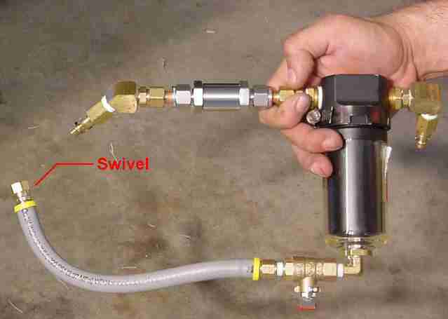
Figure 11
Yours may look a little different than mine if you used a check valve from Brad Kilby or if you didn�t use an oil removal filter at all. That’s ok, as there are many different ways to hook it up, but the process is the same.
Here is a picture of the bracket I fabricated from 1″ x 1/8″ strap metal. This should give you some ideas to help fabricate your own if you are not “weld challenged”. See Figure 12.
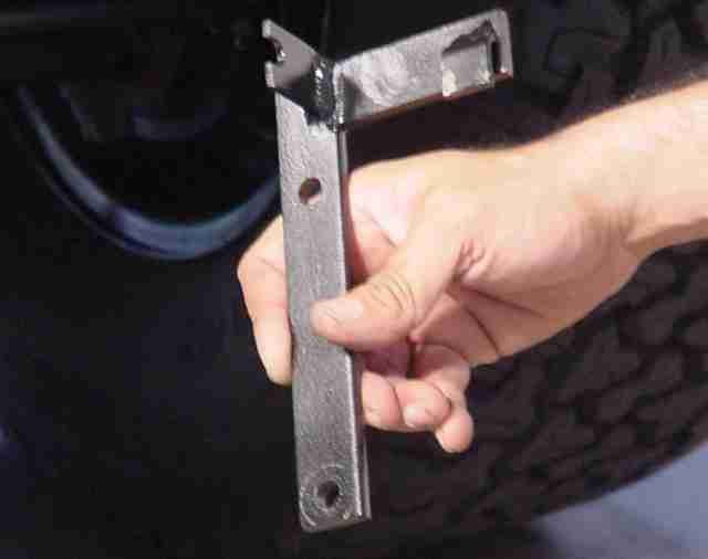
Figure 12
AIR MANIFOLD MODULE
The third module (air manifold) will now need to be assembled. I selected the manifold from Kilby Enterprises, so that is what will be discussed here. If you elected to utilize the 5-in-1 air manifold from Northern Tools, then assembly will be basically the same and both are very easy to assemble. Parts needed for this project will be the manifold, 0 – 160 psi gauge, adjustable relief valve, adjustable pressure switch, 1/4″ NPT male plug, 3/8″ NPT male plug, 3/8″ NPT male connector, 1/4″ NPT male quick connect, rubber cover for quick connect coupler, Teflon tape and the same assorted wrenches utilized from the previous assembly.
1. With Teflon tape, install a 3/8″ NPT male plug at the left end of the air manifold with the Kilby name facing you.
2. Install a 3/8″ NPT male connector on the right end of the air manifold with Teflon tape.
3. Now, with Teflon tape, install the 0 – 160 psi gauge, relief valve, pressure switch, male quick connect and last the 1/4″ NPT male plug in the desired positions.
Here’s a picture of mine. See Figure 13.

Figure 13
Again, with compressed air, pressurize the air manifold, insert the manifold into a bucket of water and check for leaks. Tighten items as required and install the rubber cover on the quick connect coupler.
Using some 1″ x 1/8″ strap metal, I fabricated a mounting bracket and attached the bracket to the manifold with 2 – 1 1/4″ 10-24 bolts, washers and nuts as shown. See Figures 14 and 15
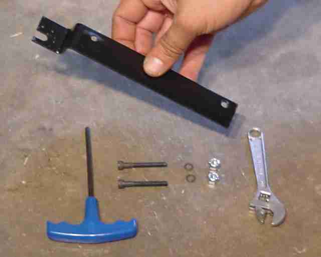
Figure 14
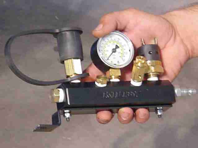
Figure 15
York OBA TJ Installation
BUMPER AIR TANK
Years ago, I had purchased a Bullet Proof FF7 bumper with the sole idea of using it as my air tank. The Bullet Proof bumper was advertised as being air tight and ready for being used for this purpose. So now was the time to see if it lived up to the advertised expectations. Needed for this part of the project are a 7/16″ drill bit, 1/4″ NPT tap, 2 – 1/4″ NPT male quick connects, a drain valve, assorted wrenches and of course Teflon tape.
1. The bumper was removed and 3 holes were drilled on the passenger side with a 7/16″ drill bit. Two holes on the very back and one on the bottom to be used for a drain valve.
The drain valve hole was strategically drilled to allow me to drill all the way through to the upper hoop so that the hoop also contributed to the overall tanks air capacity and would also be somewhat protected by the dangling clevis. See Figure 1.
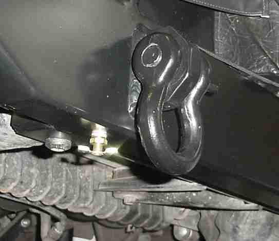
Figure 1
2. Each hole is then carefully threaded with the 1/4″ tap.
After all the holes were drilled and threaded, a small mechanics telescoping magnet (small enough to fit in the holes) was utilized to remove all the metal shavings from inside the bumper.
3. The drain valve was installed on the bottom hole and the 2 – 1/4″ NPT male quick connects were installed on the 2 remaining holes on the back of the bumper utilizing the Teflon tape.
The bumper was then pressurized and checked for leaks by inserting it into a bathtub full of water. (Believe me when I say… this is best accomplished when the wife isn’t home.) Well, after all the experience I had putting the air manifold and oil removal filter together, the quick connects and drain valve were leak free. Unfortunately though, there were two leaks (not just one) in the bumper. One at each end… so much for the advertising. Fortunately, my highly trained welding skills would only require me to grind, spot weld and check for leaks no less than 4 times before the leaks were finally eliminated. Each welded area was painstakingly prepped and repainted for that like new look. Bumper completed. See Figure 2.
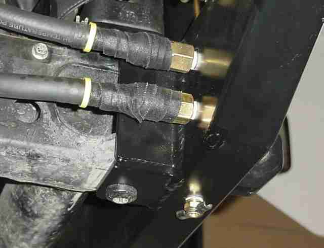
Figure 2
York OBA TJ Installation
ELECTRICAL WIRING AND CONNECTIONS
With all the components complete and bumper reinstalled, it was now time to turn my attention to the wiring. I wanted to tap some power off a keyed on/off circuit inside the vehicle to operate a relay, that operated power from a battery keyed on/off source. That way I would not have to worry about the switch handling too much power and would also insure that if the switch was left on after shutting down the jeep, it wouldn�t drain the battery.
For this part you will need approximately 20 ft. of automotive 16 gage wire, 2 – wire tap connectors, 9 – female spade connectors, 1 – male spade connector, a lighted on/off switch, Radio Shack relay, a bullet connector, electrical tape, assorted screw drivers, pliers and sockets.
1. Remove the glove box.
2. Remove the #4 (Door SW Defeat 10A) fuse located at the bottom right corner of the fuse box. This is so we can leave the doors off/open while we work and not worry about running the battery down. See Figure 1.
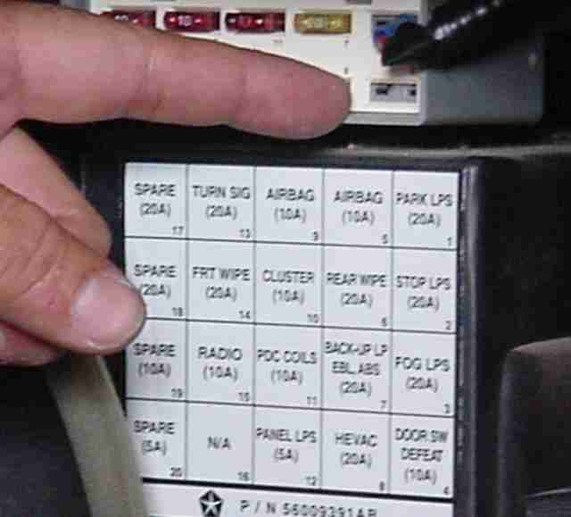
Figure 1
3. Remove the long thin panel on top of the dash that is at the bottom of the windshield. Careful, don’t break it. See Figure
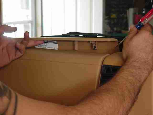
Figure 2
4. Remove the ashtray. Then remove the 3 screws that hold the radio/ heat control bezel. 2 screws are at the top and one is behind the ashtray. See Figures 3 and 4.
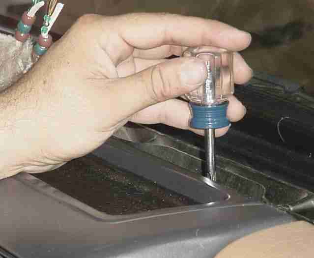
Figure 3
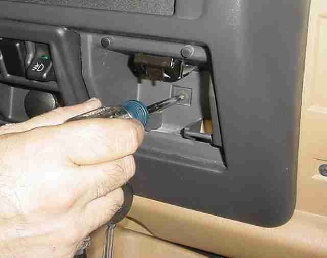
Figure 4
5. Carefully remove the bezel by pulling slightly up and back, towards you.
6. Remove the 4 screws holding the switch bezel to expose the wires. See Figure 5.
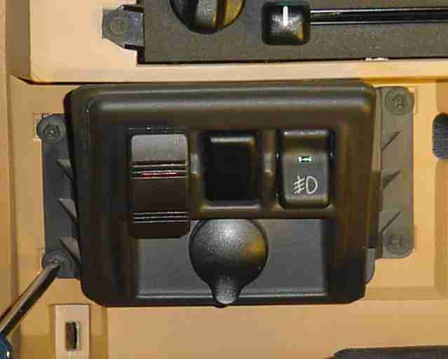
Figure 5
7. Locate the wires leading to the cigarette lighter and disconnect them. One should be black (ground) and the other should be light blue (switched on/off power).
8. Remove enough black insulation tape to allow easy access to the black and blue wires (approximately 2″ worth).
9. Cut 2 – 4″ lengths of automotive 16 gauge wire. (One red 4″ length for hot and one black 4″ length for ground.
10. Strip the two wire ends and crimp a female spade connector to the stripped ends of the red and black wires.
11. Place a wire tap connector on the blue wire and insert the 4″ red wire into the connector and securely close the wire tap connector with a pair of pliers.
12. Do the same procedure described in step 11 to the vehicle black wire using the 4″ black wire and wire tap connector.
13. Using electrical tape, dress the wires to desired perfection.
14. Remove the desired switch blank from the switch bezel and install your switch into position with the switch light at the top.
Some shaving of the switch may be required to get the switch installed properly. I preferred to shave the switch instead of my bezel incase I ever wanted to go back to stock or just change things later.
15. With what’s left of the red automotive 16 gauge wire, dress the wire neatly to and through the fire wall on the drivers side.
I went through the rubber grommet just above the steering column.
16. Strip the red wire and crimp a female spade connector to the end closest to the cigarette lighter.
17. Reconnect the original black and blue wires to the cigarette lighter.
Up to this point you should have 3 wires with spade connectors (2 – red and 1 – black) ready to hook up to the switch. The black wire provides the ground for the lighted portion of the switch and connects to the top switch spade connector. The two remaining red wires with female spade connectors are connected to the last two switch male spades. Don’t worry, it doesn’t matter which wire to which male spade on the switch. The switch just closes the circuit between the two red wires. See Figure 6.
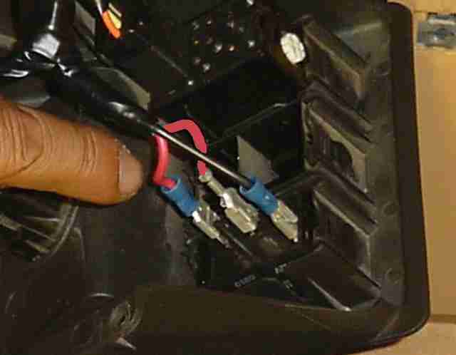
Figure 6
Time to test your work. First, insure the red wire currently in the engine bay is not touching any metal. Turn your ignition key on and turn your switch on. The lighted portion of the switch should light up. Did it light up? Super. Now leave the switch on and check for current at the end of the red wire in the engine bay with a circuit tester or multi-meter. Got current? Sweet. Turn off the ignition key and the switch and put everything back together in reverse order including the fuse and glove box. Your completed switch should look something like this: See Figure 7.
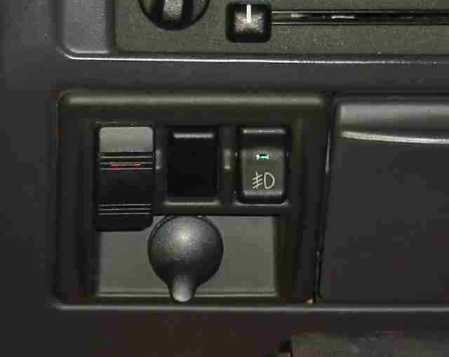
Figure 7
In the engine bay, dress the long red wire to the passenger side inner fender. I used the existing wire bundle conduit along the top of the fire wall. I first threaded the wire to the passenger fender then inserted the wire into the conduit with the other vehicle wires for that stock look. Ok, is your wire dressed? Lookin’ good.
Now select a spot and mount your relay just below the fuse/relay (Power Distribution Center PDC) box on the passenger inner fender. See Figure 8. I had two relays to mount so I fabricated a bracket to hold both relays to an existing OEM hole on the fender. See Figure 8
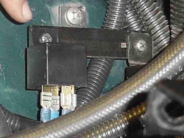
Figure 8
After mounting the relay, insure your red wire will reach this position with a few extra inches to spare and cut the red wire accordingly. Here is the wiring diagram from the back of the relay package (Radio Shack part #275-0226) that will be utilized to connect the wires to the relay. See Figure 9.
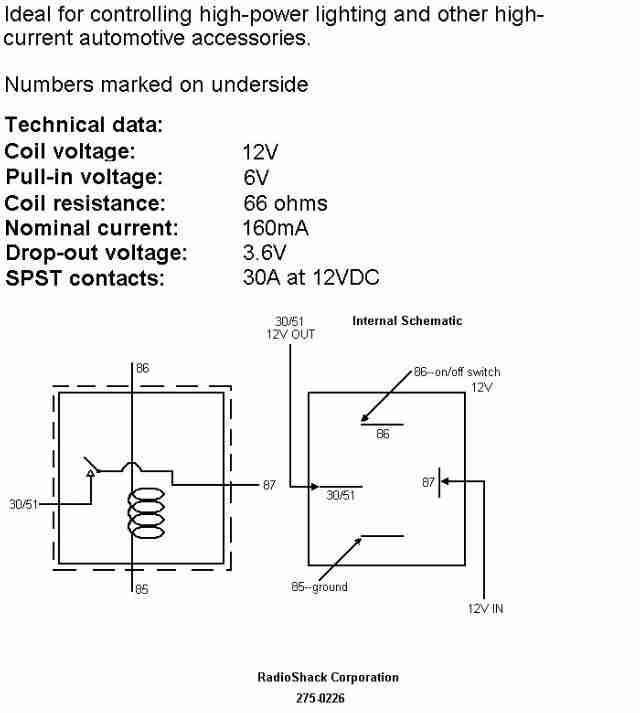
Figure 9
18. After the red wire is cut to the proper length strip the end and crimp a female spade connector to the stripped end. This wire will be the wire that operates the relay and is connected to pin 86 on the relay. Refer to Figure 9 for relay wire connections.
19. Open the PDC fuse/relay box located on the passenger inner fender.
20. Turn on the ignition key.
21. With a circuit test light or multi-meter find an empty relay slot that turns off when the ignition key is turned off.
22. Cut a length of the red automotive 16 gauge wire to go from the selected empty relay slot to the mounted relay with a few inches to spare.
23. Strip the wire at one end and crimp a male spade connector to the end just stripped. With the ignition key off insert the spade into the available slot and dress the wire to the exterior of the box and close the box lid. See Figure 10.
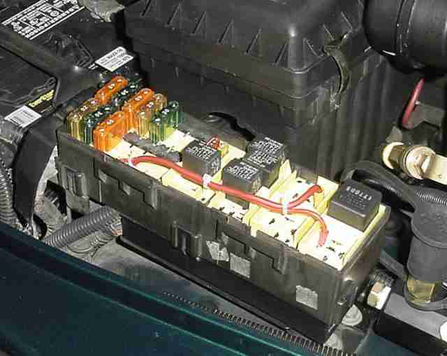
Figure 10
24. Strip the other end of the wire that comes from the PDC fuse/relay box and crimp a female spade connector to the end. This wire will be the wire to operate the compressor and connects to pin 87 on the relay. Again, refer to Figure 9 for relay wire connections.
25. Cut approximately 2 feet of 16 gauge black wire and strip one end. Crimp a 5/16″ round terminal to this end of the black wire.
26. Remove the rear PDC fuse/relay box mounting bolt and install the 5/16″ terminaled black wire end to this bolt and securely re-install the bolt. Insure the bolt is tight to effect a good ground.
27. Cut the black wire to length to reach the relay with a few extra inches to spare. Strip this end of the black wire and crimp a female spade connector to the wire. This wire will be the ground to operate the relay switch and connects to pin 85 on the relay. Again, refer to Figure 9 for relay wire connections.
At this point, you should have one unused relay terminal. This terminal will be wired to the pressure switch on the air manifold module.
York OBA TJ Installation
OBA FINAL MODULE INSTALLATION
All of the above instructions were accomplished at my leisure over the course of a months worth of weekends. This was done to insure that I had at least two days to complete a particular portion of the project and to insure that if anything went wrong I would have sufficient time to fix the problem in time for Monday morning work since my jeep was my daily driver. Once all the above preparations were complete, a two day weekend was set aside to do the next final steps.
Requirements for these final steps include the Brad Kilby bracket kit, York compressor, Air Manifold module and Oil Removal Filter/Check Valve that were all ready prepared from the previous instructions. Also required are the 3/8″ Insta-Grip hose, v-belt, Kilby alternator pulley, 4 – female Quick Connect couplers, 2 – 1/4″ NPT female hose connectors, 6 – 1/4″ NPT male hose barbs, Teflon pipe thread tape, male/female wire bullet connector, rubber mallet, wire stripper/cutter/crimper, all weather tape, masking tape, anti-seize, assorted combination wrenches, sockets extensions and ratchets.
Note: This would also be a good time to replace the number 1 sparkplug.
The instructions included in the Brad Kilby kit are very good. Follow them.
1. Disconnect the battery.
2. I applied 1″ of masking tape to the idler pulley belt tension bolt threads to mark the future reference spot I would re-tighten the idler pulley tension bolt to for proper stock belt tension.
3. Loosen the serpentine belt by loosening the idler pulley bolt. See Figure 1.
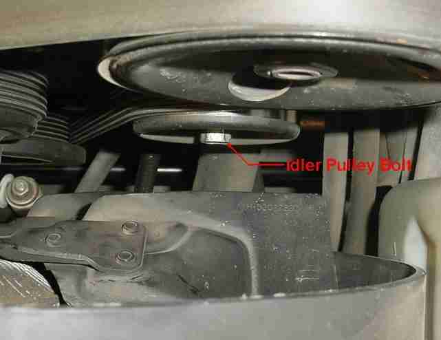
Figure 1
4. Turn the tension bolt counterclockwise until the belt is really loose. See Figure 2.
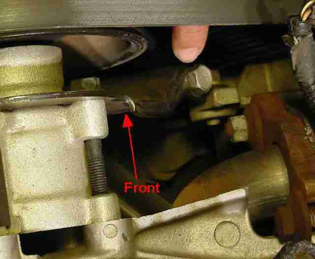
Figure 2
5. Disconnect and remove the alternator.
6. With a 7/8″ or 22 mm socket and air impact, remove the stock pulley and install the pulley included in the Kilby kit. See Figure 3.
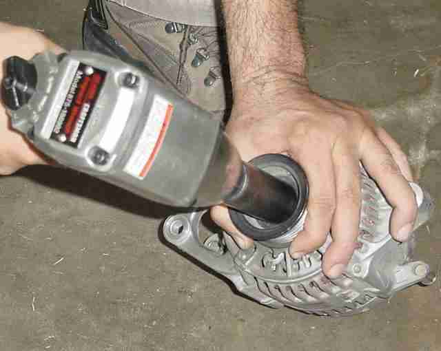
Figure 3
I’ve heard that trying to remove the pulley without an air impact can be extremely difficult and could cause damage. This is not to say that it can’t be done. If you don’t have an air impact, then take the alternator and new pulley to the nearest mechanic or automotive store to have the new pulley installed. Also, if you are going to replace the number one sparkplug this would the time to do it since the sparkplug is difficult enough to get at under normal circumstances and would be even more difficult to get at after the OBA install is complete.
7. Re-install the alternator and wire connections, torque the bolts to 41 ft. lbs and reposition the serpentine belt. Do not tighten the belt yet.
8. Remove the four factory bolts holding the AC compressor and carefully lift the compressor and insert the provided Kilby spacer between the compressor and compressor mount bracket on the two inside bolts and re-insert these two bolts loosely (a couple of turns is all) to help hold the spacer in place. See Figure 4.
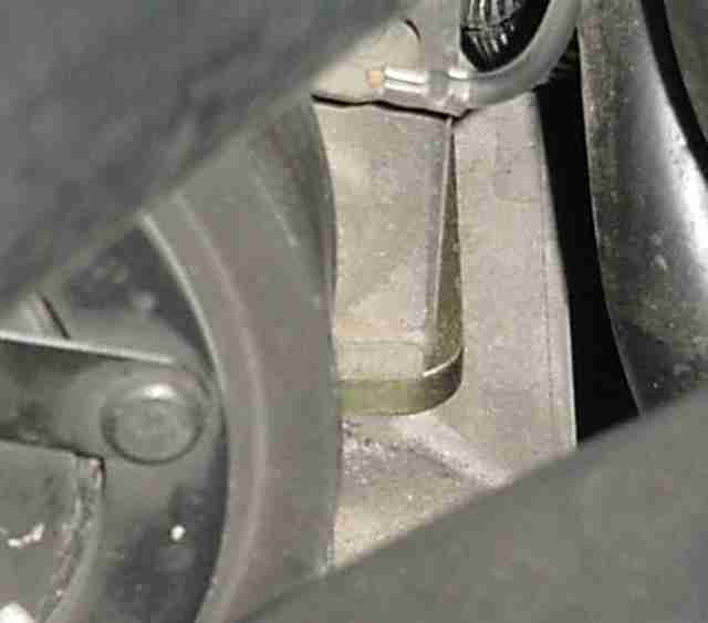
Figure 4
9. Lift the end of the compressor closest to the fender and insert the main bracket between the AC compressor and compressor mount bracket and snugly re-install the two factory bolts.
10. Now remove the first two inner factory bolts and, with anti-seize on the threads, install the two longer bolts with flat washers supplied in the Kilby kit.
11. With the 2 Kilby kit 5/16″ x 1″ bolts, 2 – nyloc nuts and 4 – flat washers secure the support bracket to the main bracket, make the necessary final adjustments and tighten all six bolts. The four compressor bolts should be tightened to 21 ft. lbs. See Figure 5.
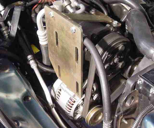
Figure 5
CAUTION. Do not over tighten the four compressor bolts as they are easily striped.
12. Check the AC line on top of the compressor that sits next to the main bracket. Mine required a minor adjustment (1/4″ or so) to insure the AC line was clear of the main bracket.
13. Install the York compressor to the main bracket utilizing the four provided 3/8″ x 1″ bolts and washers with anti-seize applied to the threads.
14. Re-tighten the serpentine belt to the previously marked position and tighten the idler pulley bolt.
I felt it necessary to check for fender and hood clearance and was glad I did. By purchasing belts made by different manufacturers and keeping all receipts, I had a selection of different length belts. It may also be necessary to purchase v-belts that are 1/4″ to 1/2″ longer or shorter for a wider selection. The idea was to raise the compressor as high as possible to tighten the belt and still have at least 1/2″ of hood clearance. I was determined to not have to cut my fender for clearance between the compressor and the fender.
I used clay between the hood and compressor fittings to determine hood clearance as well as a drop light in the engine bay to see what I was doing as I slowly closed the hood with each new belt tried. This was a long drawn out process of changing out belts till I found one that gave the best clearance between the hood, York compressor and fender. This process insured I would not need to cut the fender. However, when all was done, there was still some question about the clearance between the York compressor and the fender.
A trustworthy person was required to do one last check of the fender to compressor clearance. I had this person (my wife) set the parking brake and start the engine and put the vehicle in gear. While I watched the clearance between the compressor and fender, rpms were taken up to approximately 1700. The engine would torque to the passenger side at the higher rpms. What I found was that the York just barely touched the fender, in the position indicated (See Figure 6), leaving the smallest little scratch right where I needed to make the required adjustments.
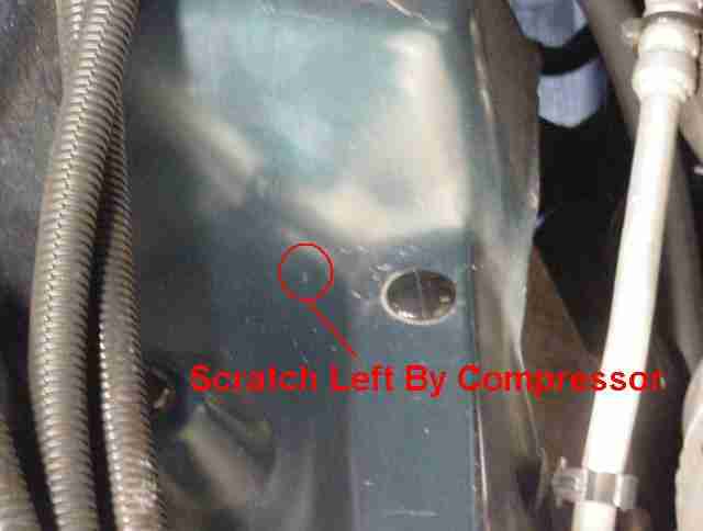
Figure 6
The compressor was removed and with a rubber mallet (so the fender wouldn’t be scratched) I pounded the area that the compressor contacted until I had 1/2″ clearance with the engine torqued. This took several attempts of installing and removing the compressor and v-belt until I was satisfied with the results. See Figure 7.
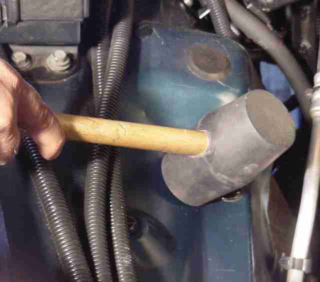
Figure 7
York compressor installed, all bolts and belts rechecked and one last check of the clearances, it was now time to start getting excited. Wow, How cool is this? See Figure 8.
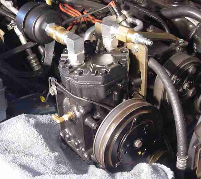
Figure 8
15. Install the previously fabricated oil removal filter/check valve bracket to the compressor and mount the oil removal filter/check valve module into place. Also connect the oil removal filter return line to the oil fill plug adapter.