Jeeps were made to go off-road…..we all know that. Winches were made to recover the Jeep when the driver either thought the Jeep should go further off-road or simply wasn’t paying attention and got stuck. If you drive off-road and you don’t have a winch, it is only a matter of time before you get one. Once you do, you’ll want an in-cab remote control. Sure, you can get by without one, but having one mounted on your dash is just plain handy. Anyone that uses an in-cab controller will vouch for that. However, having one installed that came from The 12VoltGuy is just plain cool. There isn’t another one made that looks as good nor functions as well as the one that Darren puts together.
I exchanged several e-mails with Darren prior to his shipping the winch control and install kit. He answered all my questions (and asked one or two), provided me with some pics to help answer a question, and was always quick in returning a response. I got the distinct impression that he was genuinely interested in my getting exactly what I wanted. In other words, customer service was great!
When the parts arrived by priority mail, I opened the box to find everything carefully packed in bubble wrap and newspaper. The small parts were packaged in two manila envelopes. Unlike some packages I’ve received from other vendors, this one had no parts rattling around in the bottom….that I like!
NOTE: Please note that the installation kit is sold separately and is not included with the winch control panel.
The quality of the parts appear second to none. These aren’t your typical Radio Shack cheap-o components. Yeah, you might be able to build it cheaper, but it won’t look this good nor be of better quality. The wire size is more than adequate for the current draw. The connectors are fully insulated.
But enough of me telling you about it….let’s get to the install.
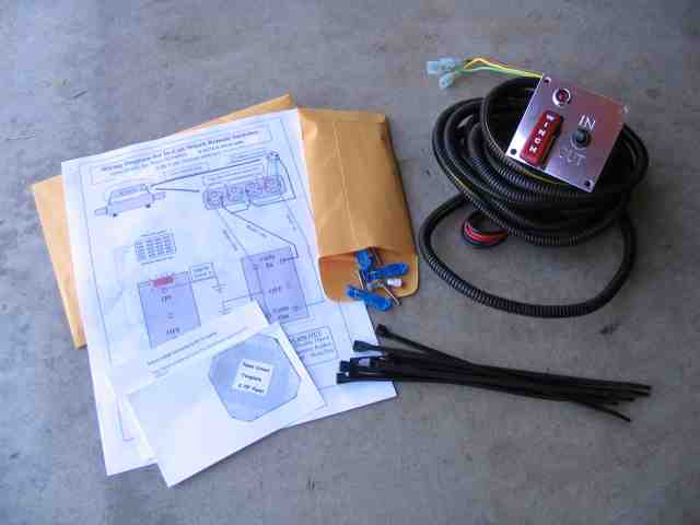
The kit includes virtually everything you should need to have a successful installation. A well drawn wiring diagram is included which details the switch panel and the wiring going to the solenoids in the Warn winch. I have a Warn XD 9000i winch and the diagram included was specifically for that model (obviously the results from one of the questions asked before the package shipped). I particularly liked the template that was printed on card stock. Rather than cutting the template out of your install documentation, Darren put it on lightweight stock which was handy. Cable ties, power taps, and mounting hardware rounded out the kit. Another thing I appreciated was the wire loom covering the wires that go through the firewall and connects to the winch. Saved me having to use my own!
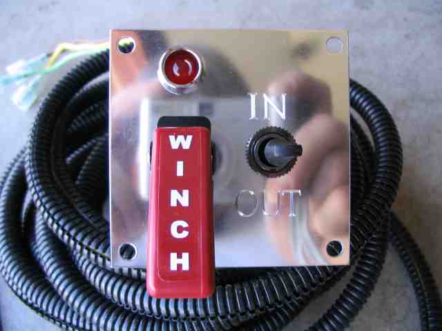
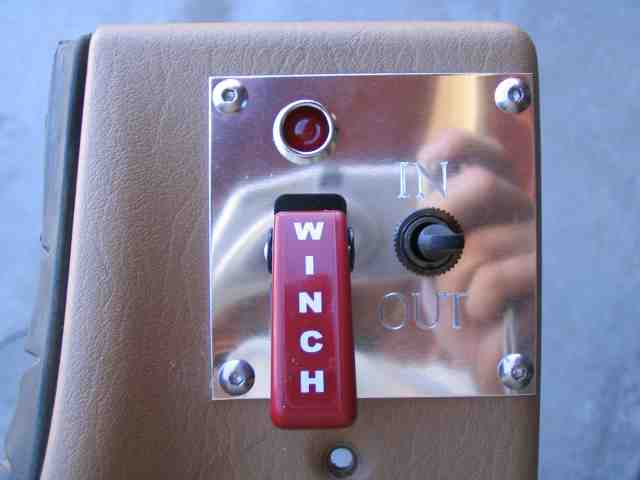
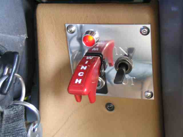
A close-up of the control panel. The LED, above the red switch, illuminates when the switch is turned on. After that, it is just a matter of selecting IN or OUT to control the winch direction. If the red winch switch is not “armed”, the IN/OUT switch will do nothing. To help reduce the possibility of someone reaching inside your Jeep and playing with the controls when you are not there, you can wire the controller to a switched ignition source (be sure the source is also fused). Unless you leave the keys in the ignition, the winch control will be disabled.
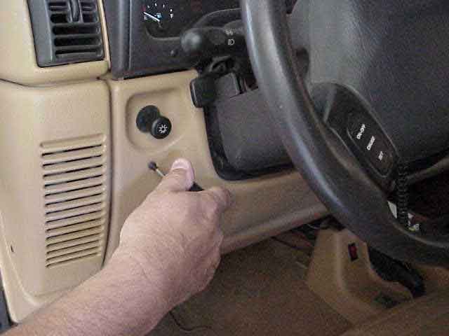
It was decided to mount the panel on the lower dash panel, opposite the location with there headlight switch is located. To remove the dash panel, remove the two Phillips screws so you can slide the dash panel over the head light switch.
If you have not already done so, disconnect the negative lead of the battery and the winch. You don’t want things coming on in the middle of doing a wiring project if a wire gets away from you. That would NOT be cool.
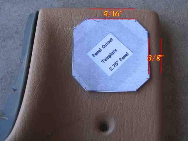
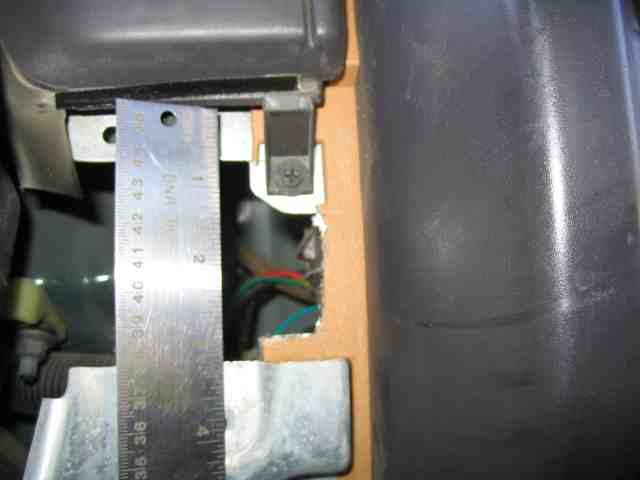
With the dash panel removed, it is time to mark and cut the hole. While I don’t have the template properly positioned in the above pic, the measurements are correct. The top edge of the template is 9/16″ down and the right hand edge is 3/8″ in from the edge of the dash panel. I used a fine line marker to trace the shape of the template on the dash panel.
NOTE: This is a good place to note that the dash panels have changed contour a bit over the years. I know that at least the ’03 and newer dash panels are different than my old ’98. The point is…..take your time and do some test fits before you commit to cutting the dash. Because my dash is contoured, I had to remove some of the substructure behind the dash (more on that later). This project is a measure 5 times, cut once kind of thing. Take your time, check and double check, and it should go OK.
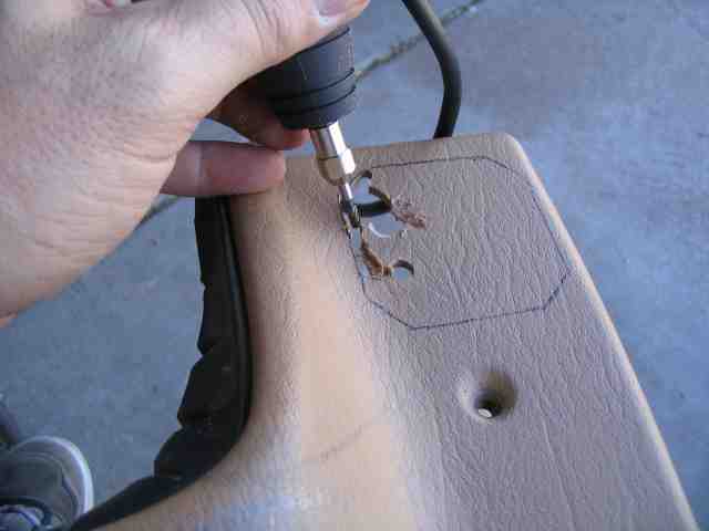
I used my Dremel tool to cut the dash panel. It was a rotary cutter bit. I had to take my time as I found that the plastic kind of melted back together behind the bit. I would cut a 1/2″ or so, then go back through it again to clean it up. Worked OK. Keep your hand steady….brace it if you need to ensure a clean and even cut.
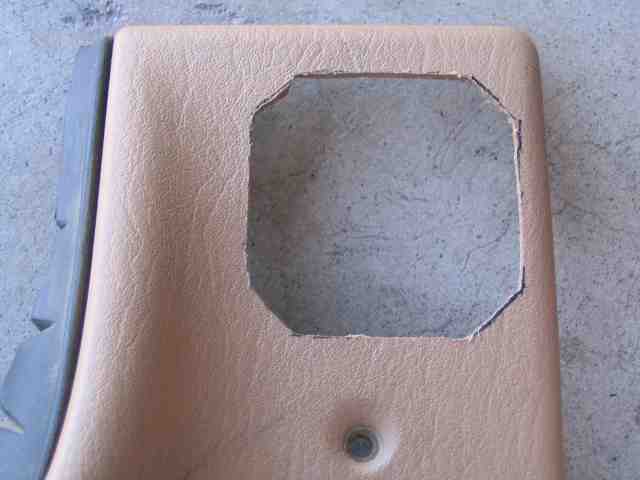
The results of the Dremel tool turned out well. It doesn’t have to be perfect since the control panel will be mounted over the cutout area. I used a rough cut file to smooth up the sides a bit.
In-Cab Winch Remote Control
With the cut out done, I placed the dash panel back into position and did some test fits. Because of the contoured shape, the cutout can not be placed any further to the left. This means that a bit of the substructure needs to be trimmed back (not totally removed) so the IN/OUT switch will have adequate clearance behind the dash.
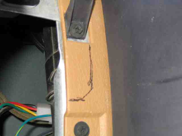
While the dash was in place, I transferred the cutout to the substructure. A little trimming here allow the control panel to mount correctly.
I used a hacksaw, one of those designed for small spaces, (I keep it in my trail tool bag) to make the two horizontal cuts and the little trimming by the Phillips screw. I used the Dremel to make the vertical cut along the ride edge. It was rather ragged and so was followed by a few minutes with the file. The last thing I wanted to do was slice a finger while doing the test fitting, wiring stuff, etc.
After the substructure was cut, I spent a bit more time test fitting the panel in the dash, ensuring there was adequate clearance. I didn’t want a switch terminal to contact any metal in the dash area.
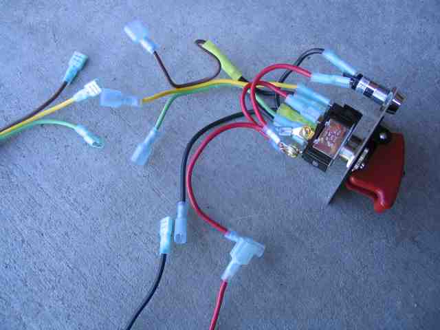
This next step was not something that Darren had planned on but I thought it was a good modification so I went ahead with it. Once the control panel wires are fed through the dash panel and then the firewall, removal of the plastic dash is going to be rather bothersome unless a LOT of slack cable is left behind the dash. I opted to cut the control panel wires and crimp on insulated connectors. This allows me to have just a little slack in the wiring and if I need to remove the dash panel (with the control panel bolted to it), I can unplug the wiring harness at the connectors, allowing me to completely remove the dash panel from the vehicle and gain access to the lower dash area. Since all five wires are different colors, reconnection is easy.
The four mounting holes were drilled in the dash panel. The control panel was finally attached to the dash panel using the supplied mounting hardware. Darren provides nutserts in the kit. They were not “set” in the dash panel as it was doubtful that they would work as intended. Instead, I used them just like regular nuts, which worked out fine.
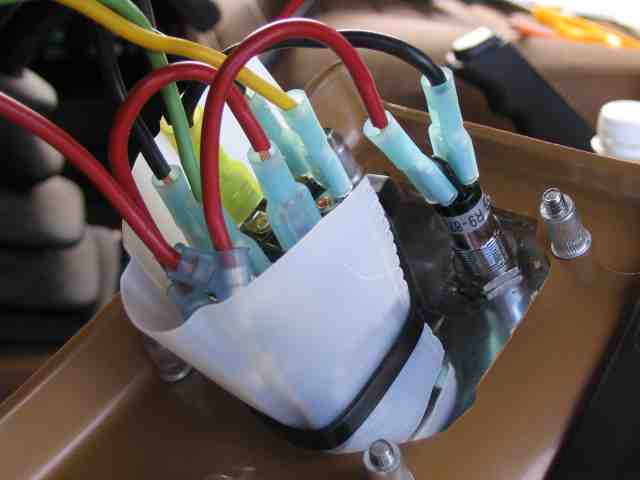
I’ll usually take a conservative approach, when I feel it necessary, and so I decided to make certain that nothing came in contact with the metal substructure. It is probably not needed but it took me all of a minute to do it. I cut a piece of plastic from an empty orange juice container and secured it in place, around the two switches, with a zip tie. Quick and easy and it gives me the peace of mind when clearance is tight.
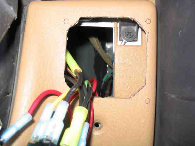
With the control panel now mounted to the dash panel, it was time to hook up two of the control panel wires. The panel requires both +12V and a ground connection for proper operation. I removed the metal panel, retained by four screws, that is positioned directly behind the plastic dash panel. I had previously tapped a fused +12V switched ignition wire under the dash for another project. I recycled this connection to also be used for the control panel. The panel’s ground wire was slipped under a screw that was screwed into the substructure. I used a voltmeter to verify that the connections were good before buttoning things up.
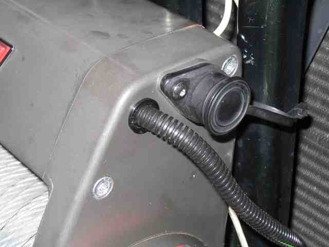
The last task on this side of the firewall was to feed the winch control wires through the firewall. I used the same point that most everyone else uses….the oval rubber plug on the firewall, located just above the accelerator pedal. I cut a small slit into the rubber plug and pushed the wires through from the engine compartment. The connectors I had previously installed were plugged into the mating connectors on the control panel.
All that remained was to attach the three wires to the winch itself.
In-Cab Winch Remote Control
Depending on what brand and model of winch you have, this will vary from unit to unit. If yours is different, you’ll have to dig up a diagram or see if Darren has the info you need to make the connections.
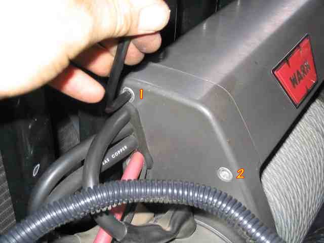
To remove the cover on the Warn XD9000i, remove the two bolts located at the top rear of the winch. It is labeld as #1 in the above pic. You will also most likely need to loosen the two bolts located at the front of the winch. This is labeled as #2 in the above pic.
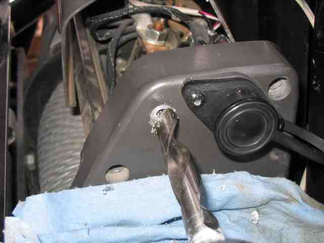
With the cover removed, it is time to mark and drill your access hole. I put mine on the end of the winch. You could also mount it to the cover that you just removed. Your choice here, what ever you want to do.
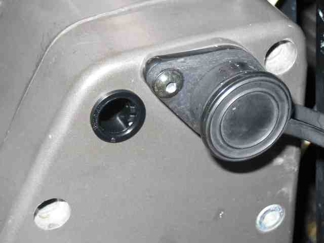
The largest drill bit I had that fit my 3/8″ drill motor was 1/2″. This is big enough for the inside diameter of the grommet that Darren supplies but not quite big enough for the grommet to fit into. Not a problem, a couple of minutes with a round file opened up the hole very quickly. I have a step drill that goes well past that size but it is made for thinner material. Anyway, it was just a couple of minutes before I had the grommet mounted.
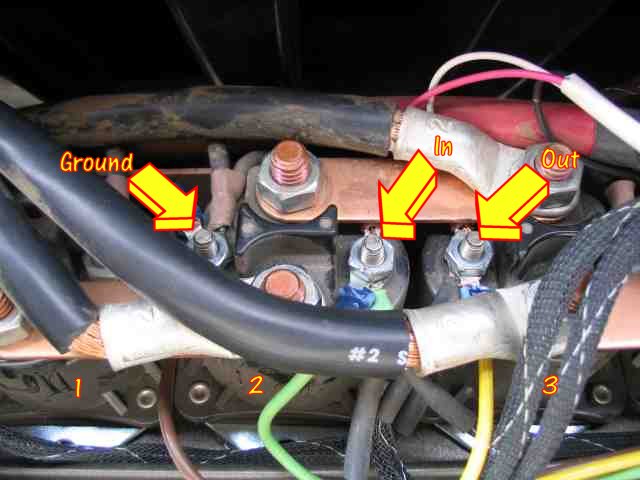
Follow the wiring diagram for your winch. Here are the connections for my particular Warn winch. The solenoids are numbered 1 through 4, left to right, as one stands in front of the TJ looking at the grill. Pay no attention to the white cable in the upper right corner of the picture as it has nothing to do with this project. I crimped small ring terminals onto the 3 wires coming from the control panel and then attached them to the appropriate terminals on the winch solenoids.
While the Warn housing is certainly not waterproof, I still wanted to keep as much moisture out as I could now that I introduced another hole in the case. Using a tube of RTV, I applied some around the inside of the case where the newly connected control wires enter the housing. Should the front end go under for a bit, it will certainly reduce the amount of water that can get into where the solenoids are located.
With the winch cover replaced, I rechecked everything one more time. With no fuses in the winch system, I didn’t really want a wiring error to cause a melt down in my Jeep. Everything looked good so I reconnected the cables to the battery that I had removed earlier.
Time to test out the system. I had my wife hop into the driver’s seat and turn on the ignition key. The winch switch cover was lifted and she flipped on the power switch. As I held the strap at the end of the winch cable, she bumped the control switch to the OUT position. Yes sir, the cable rolled out of the fairlead. A little bump of the switch to the IN position retrieved the winch cable.
That is about it. It is not a difficult installation….you just want to take your time while mounting the control panel so as to get it located correctly and looking good.
Many thanks to Darren at 12VoltGuy.com for a well thought out kit. It looks great and works as advertised. While you are at his web site, check out the other items he has available. From what I’ve heard, if he doesn’t have it in his inventory, he can most likely build it for you. Tell him you read about it here.
Good trails and remember to TREADLightly!