I always look forward to Saturdays (because it is the start of my normal three day weekend). I work a four 10 hour days shift, usually Tuesday – Friday so when quitting time rolls around on Friday, I look forward to not being back in the office until Tuesday morning. This particular Saturday was going to be a more fun than most because a good friend of mine, MikeW, that I never get to spend enough time with was coming over at 9:00 AM. We had talked earlier in the week about doing some Jeep wrenching and some computer stuff. When I told him I had gotten my new Throttle Winch Control from Kwan Motorsystems in San Jose, CA., Mike was more than ready to lend a hand. So, I got up early on Saturday, tossed the dogs in the back of the TJ, and headed out to the desert to let them blow off some steam. We got back at about 8:30 AM which gave me enough time to get things set up for Mike’s arrival. At 9:00, Mike pulled up in his TJ and we got started on the day’s agenda.
You might be wondering just what the heck a Throttle Winch Control (TWC) is suppose to do. It is a dual purpose “black box” controller that functions as a throttle control and also as a winch controller. More correctly said, it is a fully electronic MOSFET controller that interfaces with your factory TJ cruise control switches to do all its cool stuff. The cruise control switches on the left side of the steering wheel, ON/OFF and SET, are used for the winch. ON/OFF becomes Winch Out (easy to remember….Out is an “O” word and goes with On/Off). The SET switch powers the winch in. On the right side of the steering wheel, RESUME/ACCEL increases engine RPM, COAST decreases it, and CANCEL clears any RPM setting and restores the engine to a normal idle. When the TWC is turned on with its power switch, the throttle control mode is available and the winch functions are disabled. To also enable the winch controls, hold the SET button (left hand side of the steering wheel) down while turning on the TWC power switch. The TWC disables the factory cruise control during operation. To enable normal cruise control functionality, turn off the TWC and ignition key. When you start the engine again (with the TWC off), the factory cruise will be fully functional.
With that out of the way, lets get to the installation. Besides, Mike has been waiting now for about 15 minutes for me to get this show on the road!
There is one other thing I should mention. For some reason, Jeep decided to change some of the wiring harness in the ’03 model. The TWC install directions clearly call out the factory connector numbers and wire colors for both factory harness setups . What you will see from here on, in the pics and in my comments, are applicable to my ’98 TJ. If someone wants comments and pics for an ’03 TJ, please feel free to contact me and arrange for delivery of an ’03 Jeep. (you won’t get it back either) If you have something newer than an ’03, you will need to contact Kwan Motorsystems for details.
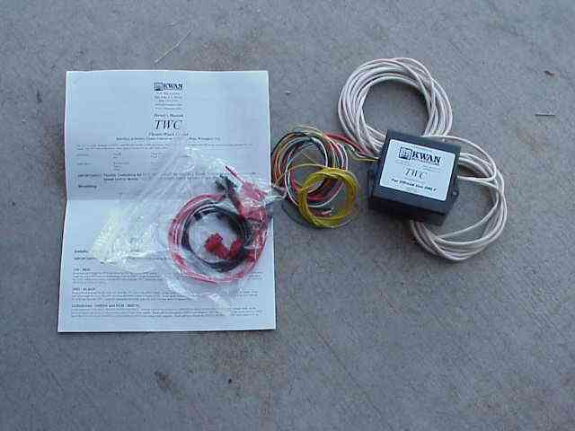
The TWC is pretty much a plug and play controller. It comes with the a generous amount of wire and cable attached to the control box. A plastic bag containing crimp on connectors, fuse, wire, screws, and a switch. The five page owner’s manual covers installation and operation of the TWC. The installation directions are detailed and include diagrams to help locate the wire connection points in your TJ and also show the pin diagrams for the factory connectors. I especially appreciated the well drawn block diagram that shows all of the TWC wire colors and their corresponding connection points in the TJ (with factory wire colors). This type of “everything at a glance” gave me a quick overview of what needed to be done without sifting through the written details. Those with an electrical background should know what I mean. That being said, I followed all of the written instructions for wiring up each group of wires to ensure I didn’t miss anything (and it serves as a good way to 2nd check yourself when hooking up the wires). I think it is safe to say that no one wishes to mess up a wiring project.
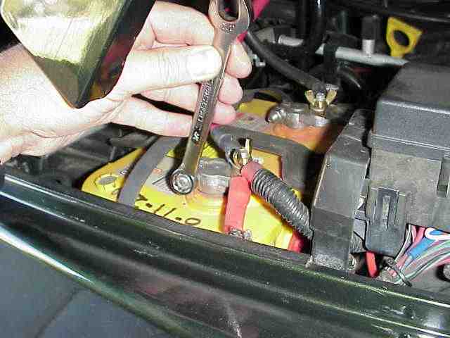
SAFETY FIRST! The installation directions say to disconnect the battery before starting on this project. You will be attaching wires to your winch control solenoids and if your winch is like mine, it is wired straight to the battery. I personally don’t want to do any 12 volt welding while I try to attach wires to the winch.

I mounted the TWC box in the vehicle on the driver’s side kick panel. The control box is not waterproof. If you think you might be taking yours for a swim (I’ve seen some of those “stuck” pictures that get posted in the on-line forums), I would suggest contacting Kwan Motorsystems for more information. It would appear that it would be fairly simple to waterproof the control box, but don’t take my word on this. Talk with the folks at Kwan and follow their suggestions.
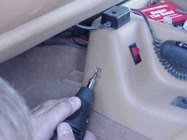
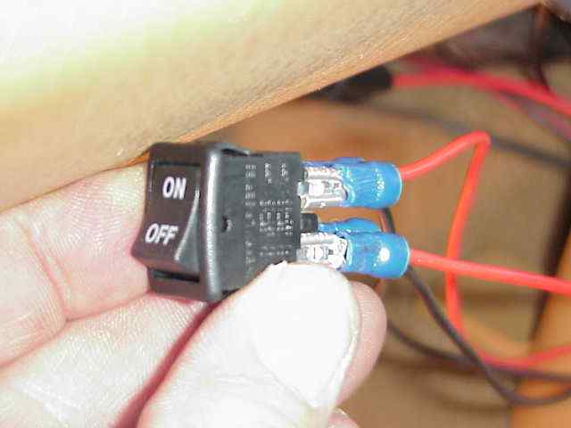
With the control box mounted, I decided to find a suitable location for the power switch. With the help of a rotary cutter (aka., Dremel tool), I cut the requisite rectangular shaped hole for the double pole single throw (DPST) switch. In case you were wondering, the other switch controls the relay for my rock lights.
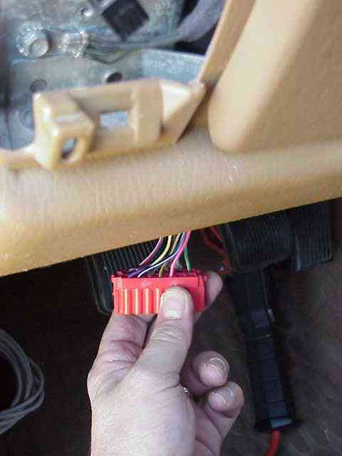
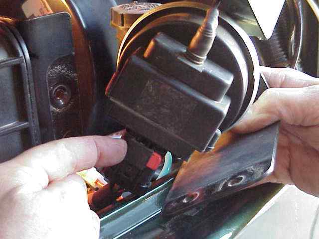
After the mounting hole for the switch was complete, it was time to start hooking up wires to their various locations. A number of wires are attached in the near vicinity of where I mounted the control box. There is a large group of factory wiring harness connectors up under the driver’s side dash area. So that I could see these a little better, I opted to removed the speaker on the driver’s side of the dash. While I made no connections via this dash opening, it allowed me to more easily identify the various connectors I would be working with and it allows a little more light to get into that dark area (of course, a trouble light will do that too). The TWC install directions do not suggest you remove the speaker, just in case you were wondering.
Throttle Winch Control
First on the list of wires to route and attach were the 12V power and ground leads. The +12V fused lead is attached to the pink wire on C204, pin 10. Its the only pink wire on this red connector so it is pretty easy to spot.
Using a crimp on splice connector, connect this pink wire using the supplied red wire and fuse holder to the power switch. The other contact on the switch is connected to the red wire coming from the TWC box.
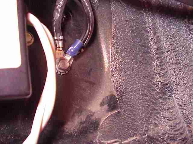
I used a factory grounding point for the ground wire coming from the power switch. It is located on the kick panel right next to where I mounted the TWC box. The black wire from the TWC box is routed to the switch and then a ground wire from the switch is connected to the above chassis ground screw.
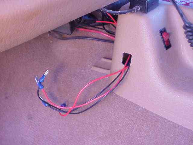
I’ve attached the crimp on spade lugs to all of the switch leads. I prefer to leave a longer pig tail, perhaps longer than some folks do. In this case, it will tuck back nicely under the center console and no one will see the extra wire. I keep a supply of zip ties and used some small ones to bundle these power wires together.
Here is a close-up of the power switch. It shows the proper connections points for the positive (red) wires. Obviously, the two negative (black) wires are connected to the other two switch terminals.
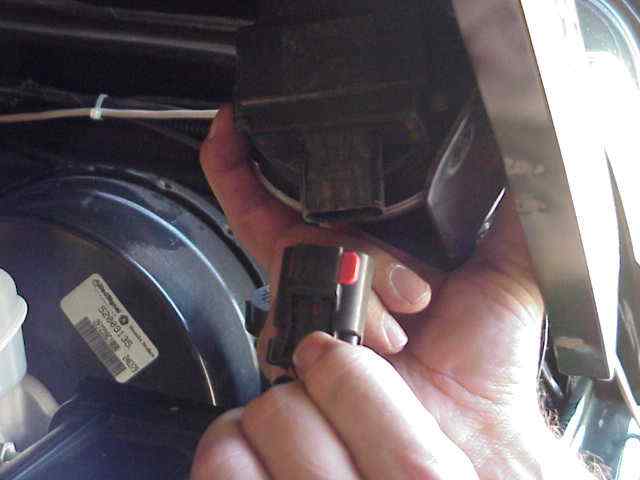
Throttle Winch Control
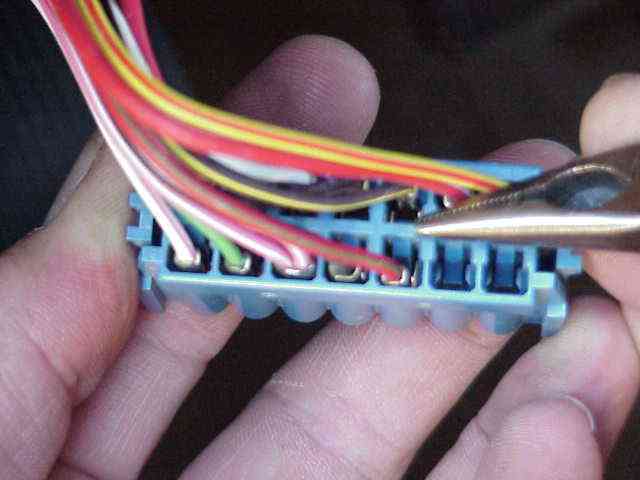
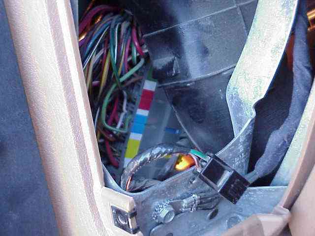
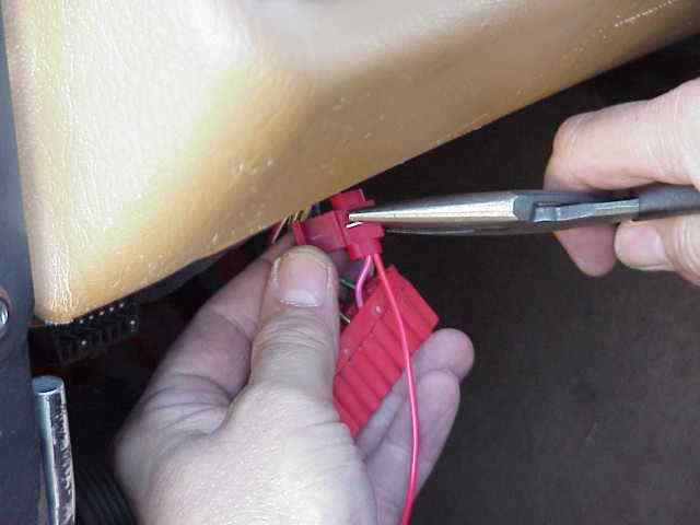
With the power leads out of the way, Mike and I turned our attention to getting the lead from the cruise control switches interfaced to the TWC box. The blue connector, C108, has a red wire with a light green tracer connected to pin 10. I am pointing to pin 10 with the needle noise pliers in the above pic.
With a small sharp knife, I removed some of the black harness wrap from the wire bundle so I could get a bit of slack for this wire. With the wire cut a couple of inches from the connector, the TWC green wire is connected to the short wire still attached to pin 10 of the connector. The TWC white wire is connected to the other end of the cut wire. Crimp on butt splices where used for both connections. I carefully re-wrapped the wire bundle with electrical tape. The butt splices cause a bit of a bulge under the tape but that is of no real concern and the tape helps keep them clean and secure. Once you are done with this wire splice, your work under the dash is complete ….YEAH! (I wish they made more room under there!)
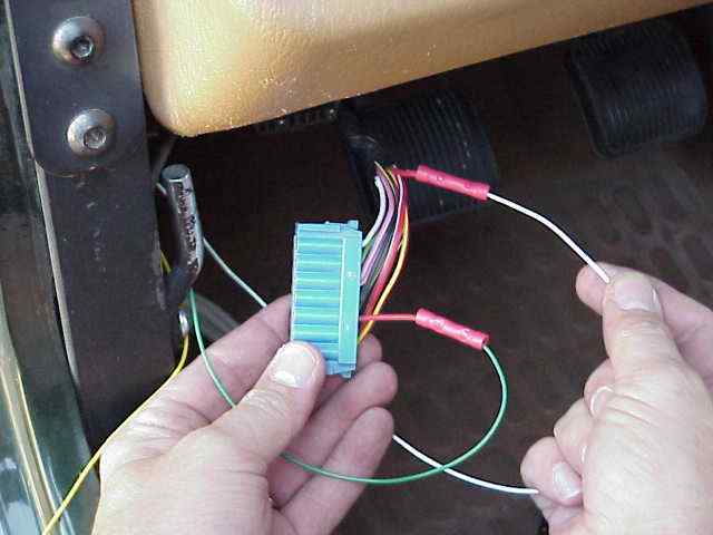
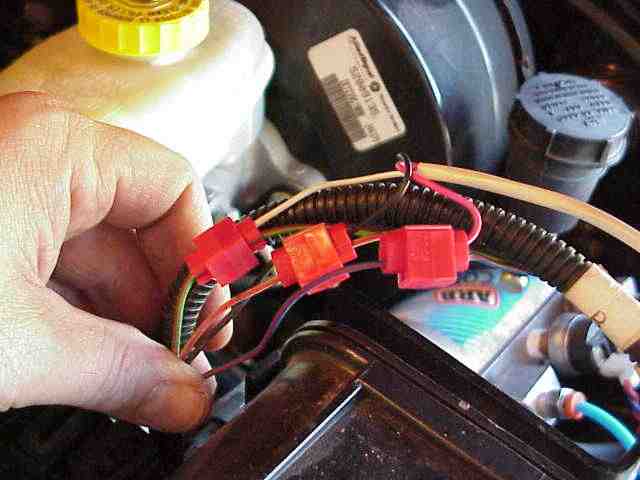
If you followed all of the steps to this point, you should have one LONG yellow wire that is not yet attached to anything and two white cables (each one with three insulated wires inside).
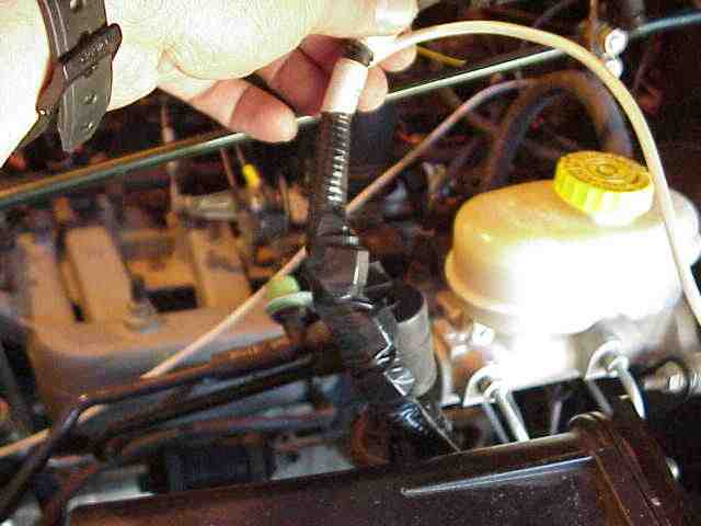
The white cables and the yellow wire are now routed to the engine compartment since this is where they must be connected. I prefer to use the large rubber plug that is located on the fire wall, just above the gas pedal. I can account for at least nine wires or cables that penetrate this rubber plug on my TJ.
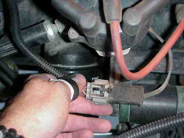
The shorter of the two white cables will be connected to the TJ’s speed control servo. The servo is located just to the driver’s side of the master cylinder. I decided to remove the factory cable from the servo as it would be easier to work on. I removed the two bolts that hold the servo to the its mounting bracket and then flipped the RED locking tab on the servo’s electrical connector (it pushes from left to right in the above picture).
With the locking tab unlocked, squeeze the plug and pull it from the servo’s connector. This is a 4 wire plug and you will be connecting 3 of these wires to the short white TWC cable.
Throttle Winch Control
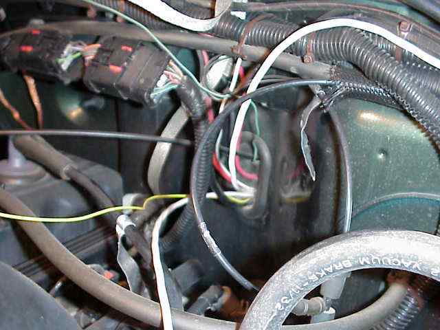
Be careful as you route these remaining wires through the engine compartment. Keep them clear of the area near the exhaust manifold as this can easily melt the insulation and cause problems. Likewise, keep your wiring clear of moving components (belts, pulleys, throttle linkages, and fan blades). Do not route your wires in such a manner that causes tight bends on sharp surfaces (sheet metal and such). Using the after market wire protectors is a good idea and provides an extra measure of protection for your wiring.
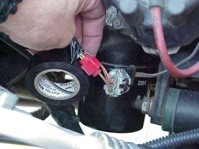
I slipped open the factory cable protector to expose three of the four wires that will be connected to the red, white, and black wires in the short white TWC cable. We used the supplied splice connectors and attached the wires according to the TWC install directions. Nothing difficult here unless you are color blind!
With the wires spliced together, electrical tape was applied and everything was wrapped with a couple layers of tape. The servo cable was then rerouted to its previous position and the speed control servo was attached to the bracket.
The remaining white TWC cable will be connected to the winch. The install directions show a typical connection for a Warn winch. I would recommend that you verify your winch connections match those in the directions. This can easily be done with an ohm meter. Connect one ohmmeter lead to the Warn winch hand controller connector. You will be using the ground, winch in, and winch out pins as shown in the directions. Connect the other ohmmeter lead to the top of the solenoids as shown in the directions. You should show 0 ohms between the appropriate connector pin and its corresponding solenoid terminal. My Warn 9000i matched the diagram in the TWC install directions. Make sure yours does too.
To remove the cover on the Warn 9000i, remove both top bolts (one on each side) from the side of the side of the winch. You may need to loosen the other two bolts (on just one side) so that the cover can be removed. If you don’t have a Warn winch with the integrated solenoids, you will have to determine how to open the solenoid box and proceed with that Winch model. Again, I’ll mention that you are just connecting three winch control wires, ground, winch in, and winch out. If you have a wiring diagram for your winch, you should be able to extract the applicable information from it.
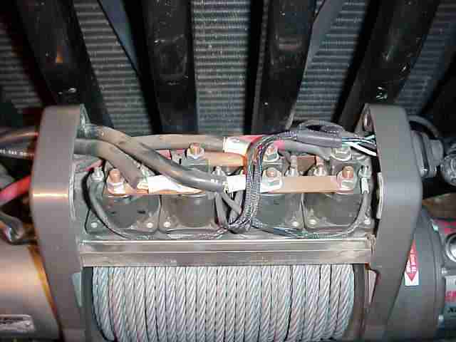
Here is a peak of what the 9000i looks like with its lid removed. Be careful when you are finished and go to replace the cover…..you don’t want to pinch any of the existing or new control wires under the lip of the cover.
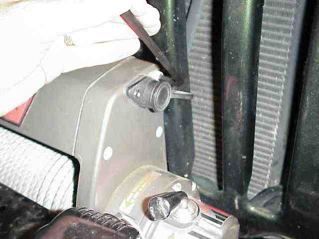
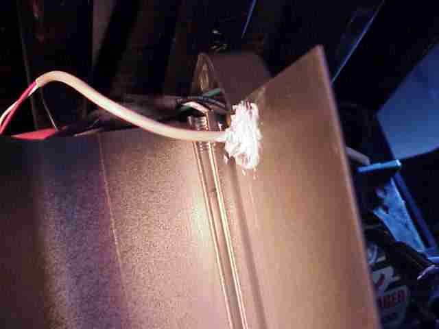
Since we had just removed the cover, Mike suggested that now would be a good time to drill a hole in the cover. He mentioned that I didn’t want to get the crimp on connectors on the end of the cable and THEN realize that we hadn’t routed the cable through the cover. Good point! We used a 1/4″ drill bit and then inserted the plastic grommet into the hole. The cable was then routed through the hole and cut to an appropriate length.
NOTE: I will confess here that I didn’t catch the sentence in the TWC install directions that said to drill the hole in the side of the winch’s solenoid compartment. IMO, it makes no difference once you are done.
Throttle Winch Control
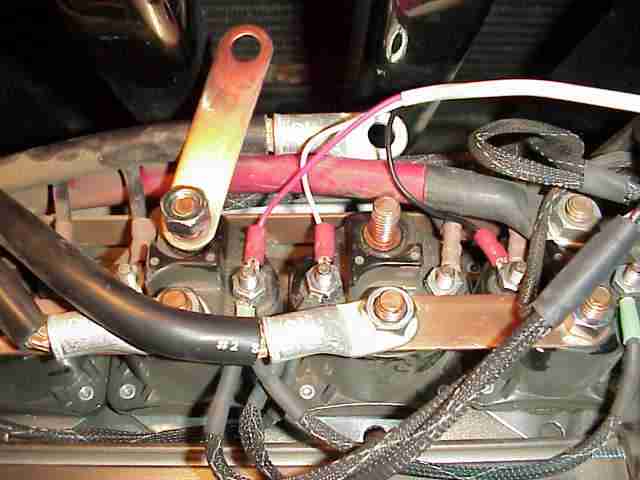
I couldn’t quite get the nut driver into the proper position so I loosened a couple of the heavy battery connections to make some room. You can see the black (ground), white (winch out), and red (winch in) wires connected to the appropriate solenoid terminals on my 9000i.
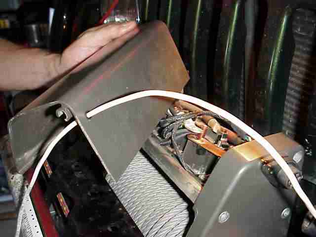
While I realize that the Warn winch cover is not water tight, we decided to put a couple dabs of silicone sealer on around the cable penetration. We also put a cable tie on the inside and outside so that the cable could not be pulled or pushed through the cover. The winch cover was carefully put back into position (make sure you don’t pinch any wires) and the bolts replaced. Make sure to tighten any bolts that were previously loosened.
You have one remaining wire, that long yellow one, from the TWC box that must be connected to the camshaft position sensor. I noticed that there was no picture for a 6 cylinder TJ with a distributor in the install directions. No biggie…the one for 4 cylinder was close enough for me. (OK, I’ll confess again and mention that I checked my ”98 FSM just to make sure I was splicing the correct wire.)
The remaining splice connector is used to attach the yellow TWC wire to the tan/yellow wire coming out of the distributor housing. Once again, I used electrical tape to wrap everything up and provide some protection. Be careful as you route the yellow wire through the engine compartment. The comments I made earlier apply equally well to this wire too.
Mike had to leave just after we finished with the winch connections so he wasn’t there for the final checkout. I am happy to report that everything worked just like the operations section of the owner’s manual stated. I started the vehicle and first tried the throttle control. It was too cool to see the engine RPMs ramp up and down as I played with the right hand group of cruise control buttons. With that out of the way, I had my wife try the other group of switches. Sure enough, the winch powered in and out, just like it was suppose to.
I put my tools away and cleaned up the plethora of zip tie snipits and called it complete! Just to make sure all was well, I took it for a drive and made sure the factory cruise control still functioned as it had. No problem there….it worked just fine.
Total install time was about 7 hours. We took our time taking pictures and discussing wire routing paths. When ever Mike and I get together, there will always be some off topic discussions which does nothing to further the progress of our wrenching project…..which was demonstrated on multiple occasions during this install. But hey, I already said I really enjoy Saturdays and especially those when I get a chance to spend it with Mike. Before I forget, thanks Mike for all the help. I look forward to the next time.
In summary, I am very pleased with the TWC from Kwan Motorsystems. I had a chance, before receiving the TWC, to exchange e-mail with them and they were most helpful in answering my questions. Although I’ve had no “problems” (and I don’t expect too), I will say that the customer support I’ve received to date (pre-sale) was second to none. I look forward to trying it out on the trail.
Update October 07,2003
After posting this write-up on the JeepsUnlimited forum, one of the members inquired about the type of interface it has with the Warn winch. It seems that Warn has an issue with one of the aftermarket wireless winch controllers that is made by another company. I contacted Kwan Motorsystems and they were nice enough to send me the following information concerning the TWC.
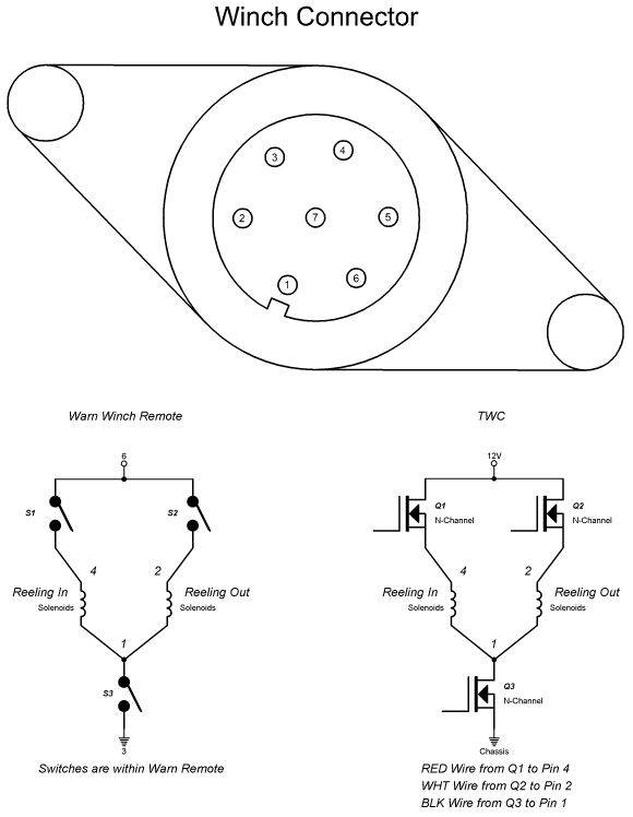
Most Warn winches (the older ones do not) have a redundant switch arrangement. I don’t know how the radio/wireless remote is designed, but the TWC has the same redundant hook up similar to the Warn remote, however it uses MOSFETs.
I’ve included a picture of the similarities between the Warn remote and the TWC. The 5 control wires are labeled 1, 2, 3, 4, 6 (total 5 wires) in reference to the pictured connector (winch connector face not the remote connector).
| When reeling in: | Warn Remote: S1 and S3 are closedTWC: Q1 and Q3 are activated. |
| When reeling out: | Warn Remote: S2 and S3 are closedTWC: Q2 and Q3 are activated. |
Since the Warn remote is portable, pins 3 and 6 on the Winch Connector supplies the +12V and GND. The TWC receives its +12V and GND through the DPST switch that was in the kit. In the diagram it’s left out but is noted as 12V and Chassis (GND). The DPST switch in the kit is on purpose. While the TWC will still function with the BLK wire connected directly to chassis, it’s main purpose is to add an additional safety precaution in case the TWC fails for some reason. It’s mainly for the throttle side of the TWC.