Tranfer case mods:
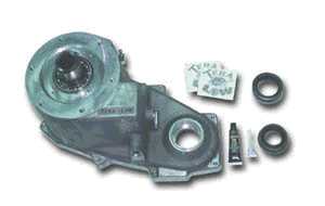 |
One of my first decisions was to go with a Tera 4:1 reduction kit for the transfer case. Even in my present configuration (32″ tires and Tera 2T lift), life on the more challenging trails would have been easier had I been able to crawl along at a slower pace. The 4.56 gears that I installed last year helped a lot, but they just didn’t provide me with the slow crawl speed I wanted. The Tera 4:1 has been in production for the NP-231 transfer case now for several years. Several of my friends run them and are very pleased with the results. As you can see, it is pretty much an entire assembly that simply replaces the front portion of the transfer case. The picture to the left is a “typical” photo of your 4:1 kit. It is not the exact one that you will get for your TJ. |
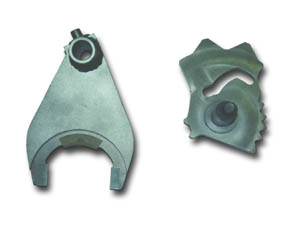 |
With the 4:1 kit will go the Tera 2LO kit. The 4:1 kit requires the transfer case to be opened up for installation (actually, you replace a significant portion of the factory t-case). Since it is going to be open, I thought the installation of the 2LO kit would be money well spent. The 2LO kit provides the t-case with one more mode….that being 2WD low range. This will give me the benefit of my new found 75:1 crawl ratio with just the rear axle being driven. This will be very helpful for the upcoming Moab trip. Turning those tight trail corners on the slick rock will be much easier now. With the Detroit Locker in the rear axle, 2LO will make for a very practical modification.There are two major parts to the Tera 2LO kit. The new range fork (show on the left) and the new sector assembly (shown on the right). The installation is composed of just replacing the existing range fork and sector assembly with the new parts. The result is an additional position on the t-case shifter….a 2L position that is located just after the 4L position. |
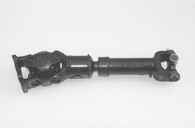 |
To take care of the vibrations that will come as a result of the 4″+ lift, I am installing a Rubicon Express (RE) Slip Yoke Eliminator (SYE) and a CV Driveshaft (show on the left). For this part of the project, I was able to skip the modification of the t-case because I bought a low mileage, SYE modified, transfer case from a local Jeeper. He recently upgraded to an Atlas II t-case, so we made a deal for his NP-231 case with the already attached SYE and CV driveshaft.
By doing it this way, it will be much easier to install the 4:1 and 2LO kits since the recipient t-case is already sitting in my garage and I won’t be under any pressure to get it done ASAP so I can drive the Jeep again. |
Suspension mods:
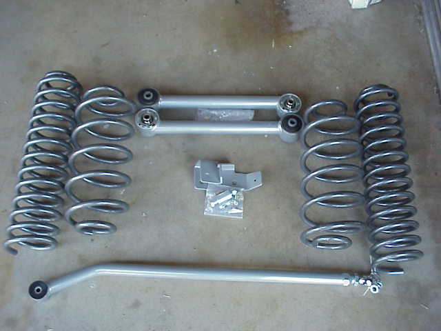
For the lift components, I have settled on components from two manufacturers. For the springs, I chose 4″ Procomp coils for both ends. These coils differ from those made by RE or Tera in that the coils are more tightly spaced which results in a higher coil count I compared these to a picture of the 4.5″ RE coils and the Procomp coils had 40% more coils in the spring. These 4″ coils provide 4″ of lift after installation, in contrast to the 4.5″~5″ often times obtained from RE or Tera springs. With a higher coil count, the coils are suppose to work less when being flexed. In the long run, they should provide a longer spring life than many of the other brands (time will tell).
The above work will all be done with the existing 32″ BFG MTs in place. Once I get everything running up to spec (ie., driveshaft vibes taken care of, front end aligned, etc.), I’ll be swapping the tires out for some Goodyear 35″ MT/Rs. I purchased three used 35″ MT/Rs from a Jeeper in Tucson the other day. I realize that sounds kind of funny. You are thinking…..”Doesn’t he need four?” Actually, I need five because my existing 32″ spare would not work as is. So, I’ll mount one of the used MT/Rs as my spare and pick up two new ones (or used ones if I come across them between now and then) for the other axle. At that point, I’ll slip in the previously mentioned coil spacers to provide the additional clearance the MT/Rs will require.
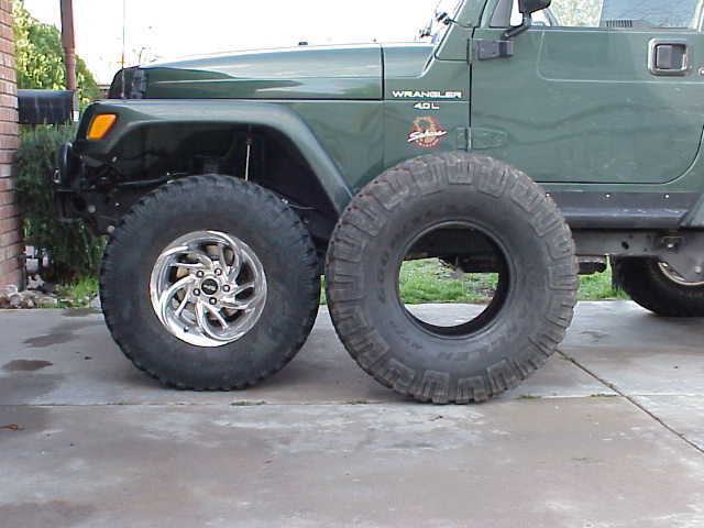
OK….so I am wondering just what they will look like once installed on Lady. Hmmm……not too bad. As you can see, they will eat up a lot of the available fender well space. Having an extra 1.5″ of clearance beneath the differentials will really be nice too.
Round #2
Well, now it is time to pretty much reverse the steps we took in getting to this point. From here on, it was pretty smooth sailing to the finish line. You won’t see quite as many photos on this half of the project, since you are now an expert on the inside of a t-case!
After removing the old and now “empty” rear case, I put the new Tera case up on the bench. I tossed the old papers, which were pretty much soaked with old ATF. Alan broke out a tube of white grease (that moly, poly, something or the other kind of grease) and I applied a bit to the outside of the front output shaft bearing.
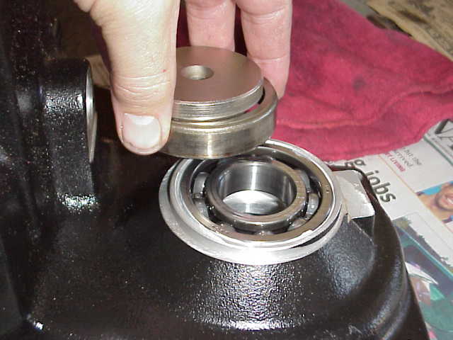
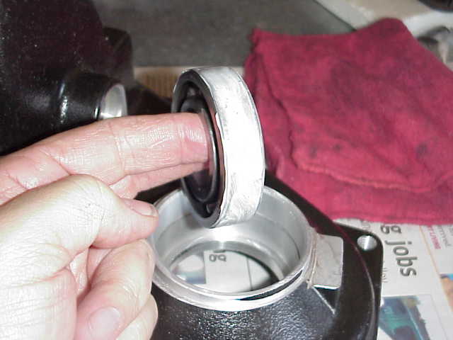
Alan has, over the years, acquired a bunch of old bearings and has taken them apart so as to claim the outer shell. He uses them as spacers to press other bearings into place. Given enough of these various sized shells, he has a pretty good selection from which to pick and choose. Here is a little something he came up with for me to start pressing the bearing into position. I finished it with a small drift punch and a ball peen hammer. Then the snap-ring was carefully put into its groove. Finally, the new replacement seal from Tera was coated with some of the grease and pushed into place with the help of a rubber shot-filled mallet. Use something like this (or rawhide or plastic) so you don’t bang up the seal body and cause it to leak.
Next, I grabbed the six case studs that we have pulled earlier and ran the threads against the wire wheel to clean up the old “goop” that was used to secure them in place.
Once the studs were cleaned up, Alan gave me a tap (we couldn’t find the proper sized thread chaser) and a I ran the holes in the new case just to make sure they were clean. This step was probably not necessary, but hey, we had the stuff available and besides that, Alan wasn’t charging me an hourly rate to use his garage!
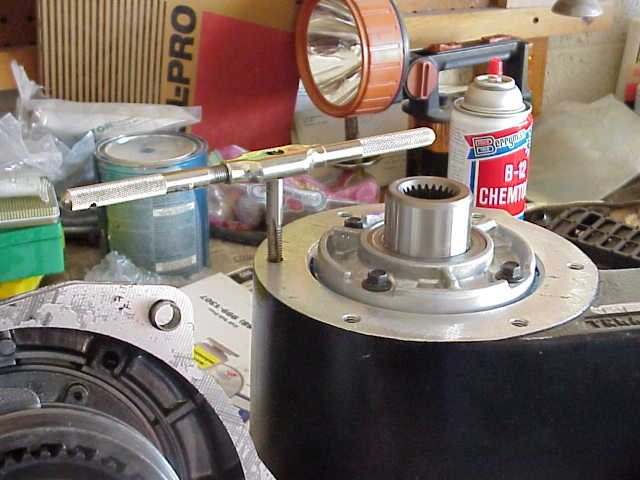
With the studs nice and clean, and the holes cleaned out, I put a couple of drops of Loctite (supplied with the 4:1 kit) on the first couple of threads on the stud and used the stud puller to screw them back into the Tera rear housing. In the photo above, I am just finishing up the last stud and will then wipe off the excess Loctite from the studs.
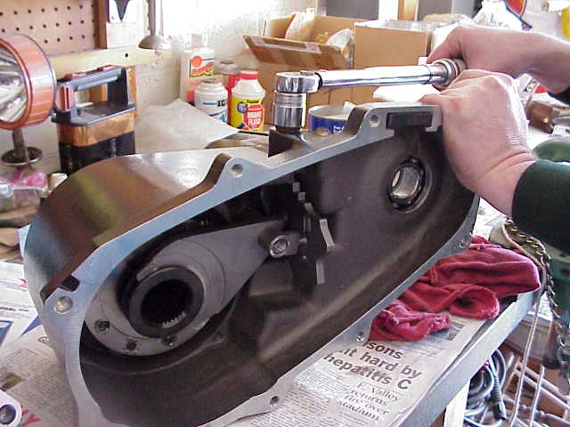
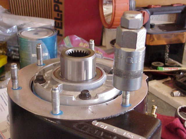
Next, I installed the shift sector and put the range fork in place. Don’t forget the o-ring and nylon bushing when you put the shift lever on the shift sector shaft. In the photo above, Alan is using the torque wrench to snug the shift sector detent cap down to the 15 ft. lbs. called for in the instructions.
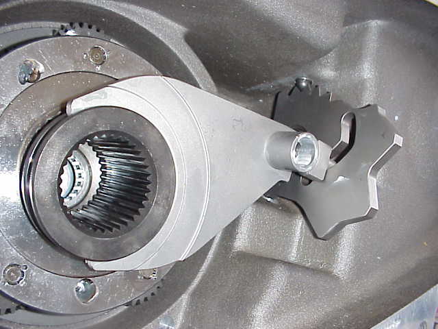
Here is a really good shot of the Tera shift sector, which is supplied with the 2LO kit. If you count the detent notches on top, you will see that there is an extra position up there when compared to the photo taken of the stock shift sector. You can also clearly see how the new Tera range fork engages the shift sector. The new range fork is also supplied with the 2LO kit.
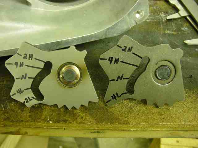
Here is another pic, sent to me by another 2LO owner, showing the difference between the factory and Tera shift sectors. The extra position for 2Low can be easily seen along with the change in the machining to accommodate it.
At this point, we put the remaining parts into the case assembly. Those included the mode fork, shift rail, mode sleeve, and mode spring. All that remained was to now put the two case sections together and pray that everything worked when we did.
I used some more of the carb cleaner and a few rags and worked on cleaning up the sealing surfaces of the front and rear sections. The rear section (new from Tera) was easy to do….a few squirts, wipe it with a dry rag, and it was done. The front section took a bit longer. Don’t rush through this process since you want to be sure you have a clean and oil free surface before you start squeezing RTV sealant onto the mating surfaces. I got everything cleaned up as good as I could and then did a second scan of the inside of the cases to make sure I had not left something out. Once satisfied that everything was as it should be, it was time to seal things up.
We stood the Tera case up, as shown in the picture above. While Alan steadied the lower case, laid a bead of RTV sealant on the mating surfaces. After that was done, I took the front case and carefully set it down on the rear case. It took a couple of minutes to get everything lined up….it little bit of wiggling things around, poking here and there with a screw driver, trying to get the gears to mesh properly, making sure none of the mode or range forks got out of whack….etc. We were down to about a 3/4″ gap between the tow cases and then everything just slipped together all at once. Hey….I wasn’t going to argue with success!
We stuffed a couple of bolts through a few holes and snugged them up just enough to ensure that things would not come apart. We then laid the t-case on its side. My first concern was to make sure nothing had slipped inside while we were assembling the cases. To test everything, I spun the input shaft while I walked the shift lever through its 5 positions…..2HI…4HI…N…4LO…2LO…. YES SIR! Everything slipped right into position with no binding or other problems. The output shafts all engaged at their proper times. I knew then that the mode/range forks and the shift sector were all working just like they should be. We then put in the remaining case bolts and torqued them to the proper spec.
Once that was done, the front output yoke was attached, but not torqued down tight. I didn’t have my factory manual with me at Alan’s and I was not sure about a very chewed up o-ring that was under the nut of the output yoke. As I write this, I still haven’t looked it up yet. I’ll have to see if it is suppose to be there and if so, I’ll need to spend $.50 or so and get a new one, since it looked pretty bad.
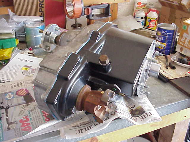
Here she be! The final product. I need to paint the front yoke and then it will be ready to swap into Lady. I am already excited about getting out on the trail and trying my new found 75:1 crawl ratio, not to mention 2LO
Round #2
List of tools used for Tera 4:1 and 2LO kit installs
| 3/8″ ratchet & 2″ extension 1/2″ ratchet3/8″ drive impact wrench 1/2″ drive impact wrench3/8″100 Ft.Lb. torque wrench 1/2″ 200 Ft.Lb. torque wrench10 MM 3/8 inch drive 12 point socket 14 MM 3/8 inch drive 6 point socket 15 MM 3/8 inch drive 6 point socket 10 MM Allen 3/8″driveLoctite supplied with 4:1 kit Permatex RTV gasket sealant Carb cleaner (to clean oily surfaces) |
7/8″ 6 point socket 1-1/8″ deep well 6 point socket7/8″ wrench 1-1/8″ wrenchAssorted long common screwdrivers Stud removal/installer tool (3/8 by 16) Seal puller Seal drivers Lead shot mallet Ball peen hammer Drift punchesBench mounted wire wheel |
Round #2
Monday came around after the weekend and the chances to do some work on Lady looked pretty good. I ‘ve worked a 4-10 schedule for many years now and always look forward to having those Mondays off.
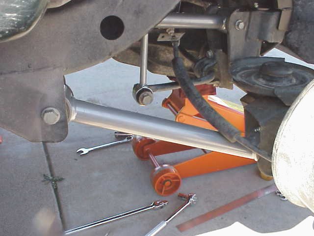
I met up with Alan a bit before lunch and we got started. I rolled out the floor jack and jack stands while Alan got a few tools ready. With the digital camera at the ready, we proceeded to install the front track bar.
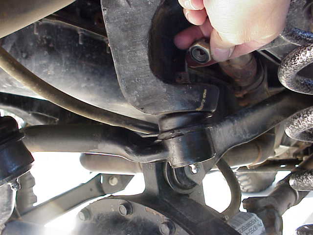
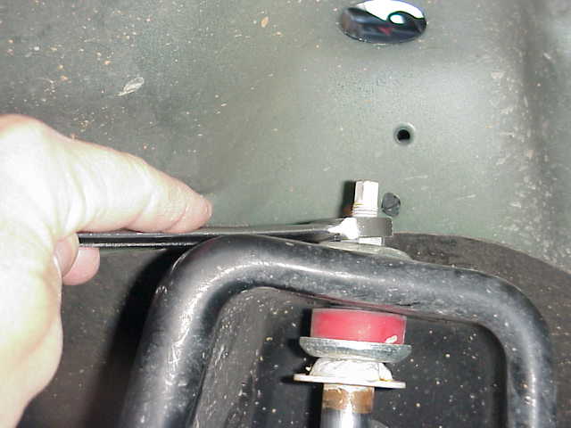
First thing to remove is the Torx 50 bolt that holds the axle end of the front track bar in place. It has one of those nuts with the welded on tab which makes it easy to keep the nut from spinning. I still would like to know why they use Torx bolts on this stuff. I hate this kind of fastener with a passion!
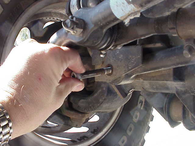
Remove the cotter pin and then the nut from the ball stud at the frame end of the track bar. The factory service manual says to use a universal puller tool to do this but neither Alan nor I happened to have one laying around (we didn’t have a clue what they even look like).
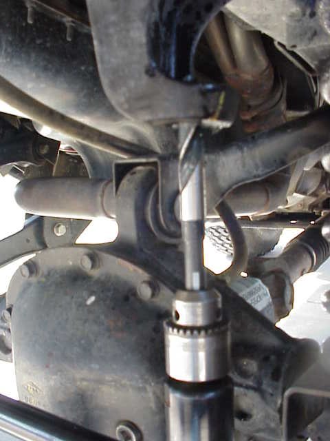
We got out a big pry bar and gave it the old college try but had no luck. Not being one to back away from a good fight, Alan suggested using the impact hammer. Knowing that this track bar was not going to be recycled made the decision to use this removal method an easy one. Alan retrieved the impact hammer and attached the whip hose to the supply hose coming from the compressor. Armed with more foot pounds of “thumping power” than is humanly reproducable, I maneuvered the impact hammer into position. I was extremely delighted when a 1 second pull on the trigger resulted in the track bar dropping out into my hand. Outstanding!
Round #2
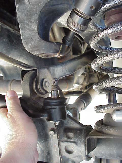
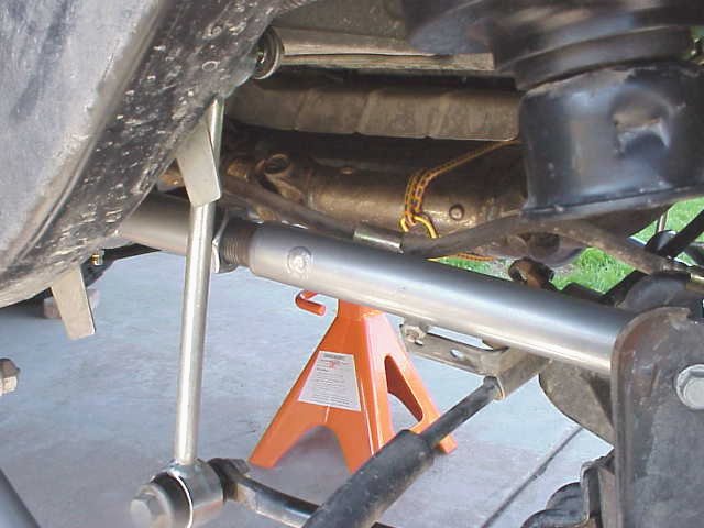
The next step, now that the old track bar was completely removed, was to drill out the old ball stud hole to 5/8″ so the bolt for the heim joint could be installed. Alan handed me a low speed (500 RPM max) air drill so I could chuck up my new Hanson drill bit (I am very proud of it….almost $25 at the local Ace Hardware store.) With a bit of oil to keep things going, I carefully drilled out the tapered hole. Keep the drill bit perpendicular to the hole in the frame and take your time. You want a nice tight fit for the new bolt. I guess it should go without saying that having a sharp bit makes this part of the job much easier.
Once you have adjusted the track bar to the proper length (I leave this to you to determine when your axle is properly centered under your chassis), assemble the spacers and the sleeve in the heim joint and bolt it into place. Note that the narrow tapered ends of the spacers should be pointing towards the heim joint. Torque this bolt to 115 ft. lbs., as specified in the manual. You will want to tighten up the jam nut on the heim joint threads at this time. The jam nut takes a 1 1/8″ wrench and I used a medium sized adjustable wrench to hold the flat surface of the heim joint in place while tightening the jam nut. You want to make sure that while tightening the jam nut, the heim joint does not get set crooked and thereby limit the amount of swivel action the joint can supply while flexing off-road.
Note: Upon the advice of a local TJ owner who has had this RE track bar for some time, I re-torqued the bolt to 165 ft. lbs (he does his at 175). I checked the grade 8 bolt specs and 175 is within safe limts. I also put a grade 8 lock washer under the nut. It snuggles in very nicely in the little indented area on the frame bracket. As I write this, I have had this in this configuration for 3 months and everything is still nice and tight. I did not use Loc-tite.
Round #2
Next on the list, with the front track bar out of the way, was the rear track bar. I had the gotten the newly designed rear bracket from RE when I got the adjustable track bar and was looking forward to the improved gas tank skid clearance that it was supposed to provide.
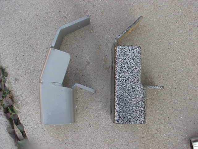
Here is a photo of the new RE bracket and the Tera bracket that I’ve been using on my 2T lift. As you can see, the RE bracket is angled more. From what I have read, this was done to help prevent binding by the track bar ( thus limiting flex) and also to help the track bar better clear the gas tank. You will see in a little bit that RE hasn’t gotten the fit for this new bracket down correctly.
Since I was putting the track bar on before I started the rest of the lift, I did this one in a slightly different fashion than when I did the Tera bracket. Please note that I am removing the Tera bracket in this write-up, so it does differ slightly from the instructions (poor as they are) that RE supplies with the bracket (there were no instructions with the track bar).
I jacked up each side of Lady and put jack stands under the frame, a few inches behind the rear edge of the transfer case skid plate. I then placed the floor jack under the rear diff housing and jacked it up just till there was a little bit of pressure being applied. I did this to provide me with another source of holding the vehicle securely in position. The jack is merely acting as a safety backup to the jack stands. Be sure to always use adequately sized jack stands when working on your vehicle in this fashion. It is not safe to only use the jack to support the entire vehicle while you work on it. Also, do not use cement blocks as jack stands. They can easily crumbled and leave you pinned under the vehicle. Once secured in place, Alan handed me the impact wrench and I proceeded to remove the lug nuts and then the tires.
In the above photo, I have already removed both of the bolts at each end of the track bar, and removed the track bar from the vehicle. I have also removed the lower shock mounting bolt so as to get a bit more room around the bracket area. Had this been done during a regular lift install, I would have also pulled the springs and the sway bar links so as to have more elbow room. You can see the upper pair of holes in Tera bracket where the track bar was installed. The remaining three bolts holding the Tera bracket to the axle bracket were removed.
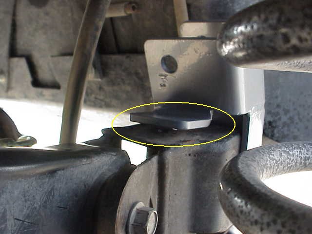
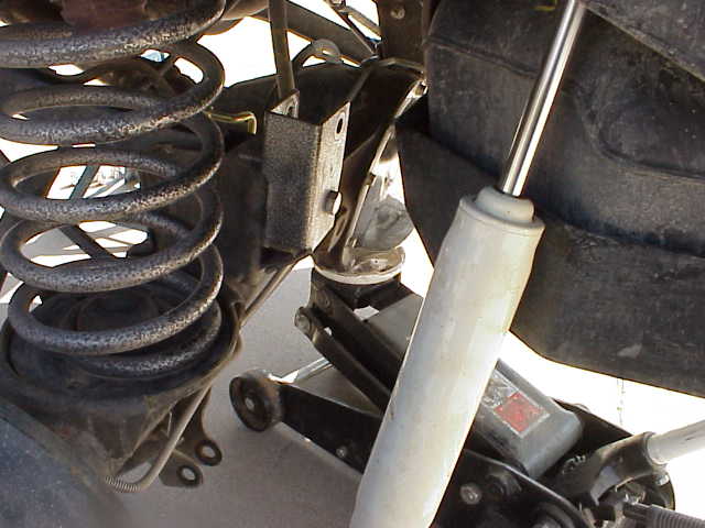
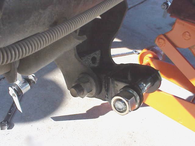
Here is a photo of the RE bracket after it has been put in place. The main 1/2″ bolt and associated spacer have been put in place and tightened so as to get a good fit between the RE bracket and the axle bracket. The 5/16″ bolt hole that attaches from the bottom of the bracket did NOT match up with the Tera bracket hole, so I drilled a new one and installed the bolt and nut and tightened them securely as well. (This is not the fault of either Tera or RE.)
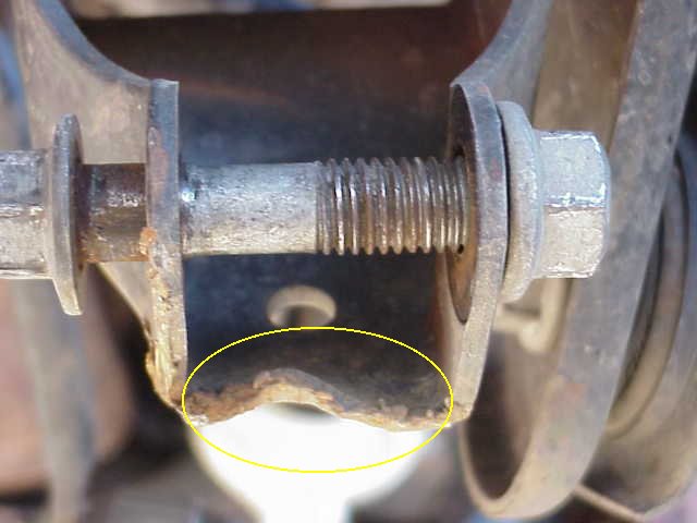
What upsets me the most is the poor fit, circled in yellow, of the RE bracket. The RE bracket should be contacting the axle bracket at this point. Instead of a nice flush fit, which the Tera bracket provided me, there is almost a 1/4″ gap as you can see in the above picture. This gap has nothing to do with the fact that I had a Tera bracket previously installed. The RE bracket is properly centered on the 1/2″ bolt that goes through the original hole that the factory track bar was bolted into. That part of the bracket, and the lower section, lines up just fine. This is simply a case of VERY POOR quality control on the part of RE. Very sad.
As I had nothing to slide under the bracket to fill this gap, I went ahead and installed the track bar. I will be filling that gap with something (not sure yet) so that it does not cause undue stress on the bracket and the bolt that goes through that part of the bracket will have something to clamp tightly onto.
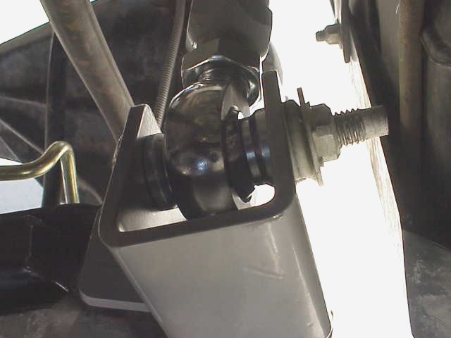
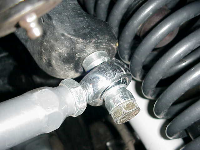
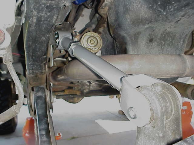
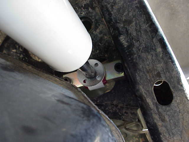
Here is the business end of the heim joint installed in the track bar bracket. Although it looks as though the Torx bolt will hit the gas tank skid, it is only because of the angle at which the picture was taken. I am going to reverse the direction of the bolt, just to be safe, but it has been that way for the past 18 months without ever contact the gas tank skid. The fact that this part of the bracket is angled more forward (away from the gas tank skid) gives it even more clearance. However, since I am going to be installing adjustable control arms on the rear axle, it makes sense to turn the bolt around just to be safe.
Note: February 22, 2000 – I called RE today and spoke in length to Marty. He acknowledged that they have had this problem in the past. Marty stated that two different hole patterns seems to be used during the ’98 TJ era which causes this to occur. He said that by ’99, DC stopped doing it. (figures!) He made provisions to send me “the other” hole patterned bracket and then realized that they only had this alternate pattern available for the 1603 version bracket (the older version). Since I have the newer 1602 bracket (with the changed angle), he said he would take an undrilled bracket and have the holes drilled in it to match my needs. I hope my verbal description was accurate enough. They took the necessary info needed to ship me the bracket. With luck, it won’t take too long. I did confirm that the bracket I have installed now could be used as is with a few washers shimmed under until the new bracket arrives.
March 3, 2001 – The new bracket from RE did in fact arrive in a few days (it really smelled of new paint….so I was pretty sure it was “fresh” off the assembly line) and I had a chance to try it out today while putting in the rest of the lift.
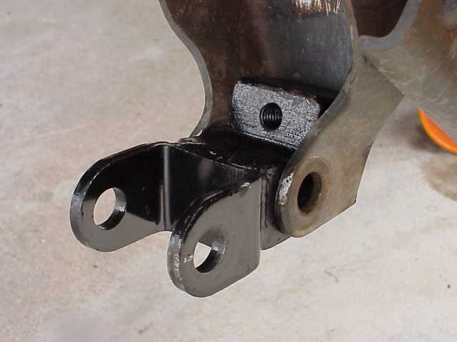
You can see the new bracket in place. They did indeed get this one right. The 1/2″ main hole is drilled 1/4″ higher up the bracket, which causes the bracket to sit 1/4″ lower on the factory bracket. I slipped the 1/2″ bolt in place, put the 5/16″ bolt up from the bottom, and then drilled a new hole for the top 5/16″ bolt. After I put the top bolt in place and started the nut on it (pretty tight in that little space if you got big fingers), it was easy to snug them all down a bit at a time and the bracket just wrapped itself around the factory mount. Thank you RE for making this right for me!
Round #2
I took the day off from work. I had an extra coming to me and the weather man was actually forecasting sunshine for a couple of days. I had missed the last weekend and I wasn’t going to miss the opportunity for this one. Alan (from my t-case and track bar work) was coming over about mid-morning and a local Jeeper (Michael) had made arrangements with me via e-mail to spend the day helping. Michael has a YJ. He was looking to get some wrenching experience and since he was new in the Phoenix area, this was a great way to meet another Jeeper. Plus, I would not turn down the opportunity to get another pair of hands under there to help with the control arms and other items.
By the time the guys had showed up, I had Lady parked in the driveway with the front end on jack stands and the tires off. The Tera 2T springs were first on the list of things to remove. We supported the front axle with the floor jack and unbolted the lower shock mounts. I had already unpinned the Tera QDs and folded them up out of the way. With the shocks removed, the was able to drop a bit further which would make pulling the springs easier.
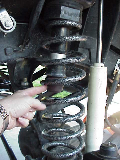
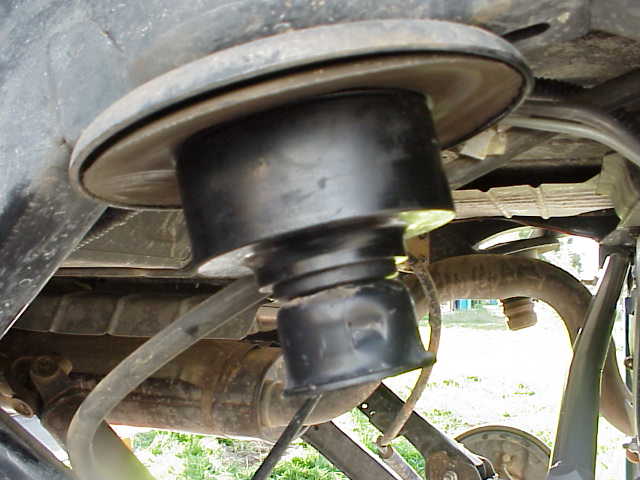
The above picture shows me pointing at the bump stop. The bump stop is physically pulled out of the bump stop cup. A 16 mm socket with an extension was used to remove the bolt holding the cup and 1″ Tera aluminum bump stop spacer. The wider spacing on these Tera 2T springs allowed us to remove all of these parts before removing the spring.
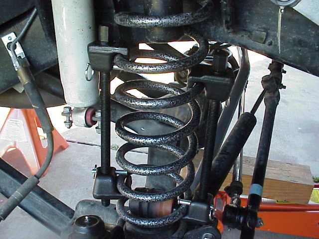
Here is a picture of the spring compressors in place. I haven’t starting tightening them yet. Some Jeepers don’t use spring compressors and claim they are dangerous, etc. I did one spring install without using them and in my opinion, that WAS dangerous. I find that if you take your time and locate the compressors properly on the spring (and lock them in place with the sliding safety pins), they do a fine job. I have done about 6 pairs of springs this way and find it to be much better than using pry bars and such.
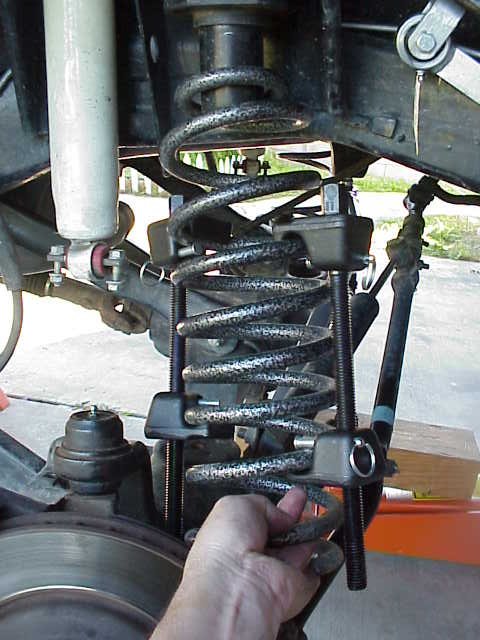
With several inches of the compressor bolts now protruding out of the bottom clamps, the spring can be lifted off of the lower pedestal with one hand. It just doesn’t get much easier than this.
Round #2
With the Tera springs now removed, we gave some thought to the bump stop requirements.
Bump stops serve two very important tasks….they limit the amount of spring compression which keeps your tires out of the fender wells, and they stop over compression of your springs. When the latter happens too much, your springs will fatigue and start to sag. At that point, your only option is to spend more money on springs and start over again (hopefully this time with the proper length bump stop).
Since I was installing 4″ springs, I ordered a set of front bump stop extensions from RE. I got the ones they use for their 4.5″ lift kit. I had already decided to leave the extra 1.75″ of spacer (factory isolator and Tera 3/4″ spacer) in place, I also decided to leave the 1″ Tera extensions in place (these came with my 2T lift). All total, I would have 3″ of additional bump stop extensions. The 2″ RE extension installs on the lower spring pedestal with a self tapping bolt. I had previously drilled these holes out so I pulled out the spare nuts and bolts box from the TJ and found a couple of suitable grade 5 bolts to use instead of the self tapping ones.
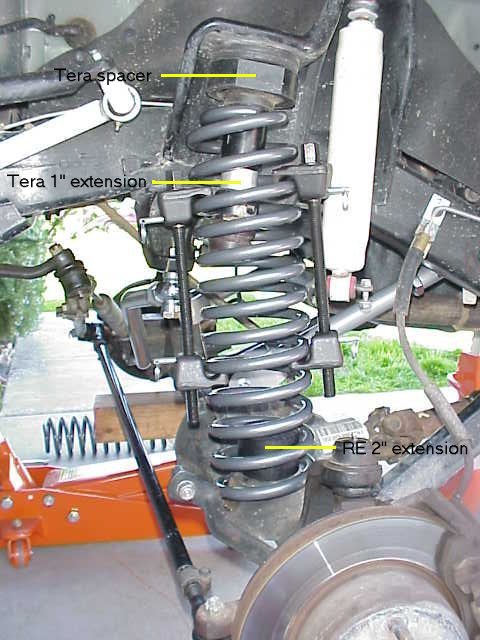
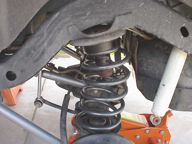
Once the parts were all in order, the upper bump stop and extension were reassembled. I opted not to bolt in the lower RE extension until after the spring was in place. Doing so before that would require an additional 2″ of spring compression which is not needed and a pain to do. The photo above shows the new 4″ Procomp spring just after it was slipped into place. As I was moving the spring into place, I slipped the RE extension up into the spring coils and slip everything into place. A few more turns of the compressor screws and the coil will be completely in place.
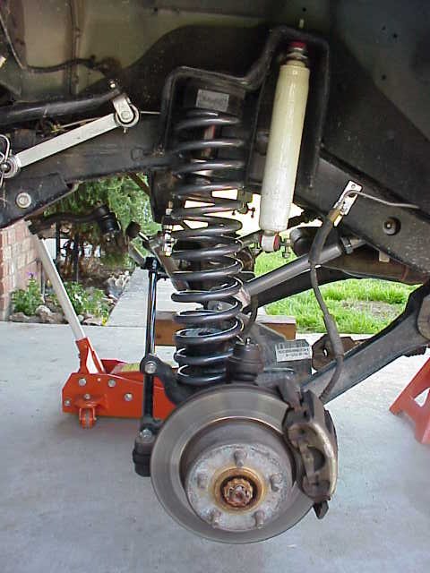
Here is the efforts of our labors. Yeah….that stock shock looks pretty darn short! With the new RE upper adjustable arms installed, we measured for shock length. Full droop to bump stop engagement was right at 8″ of travel. Once the new tires are in place, I’ll see how that works out. There will probably be a little bit of tweaking of the spacers, bump stops, adjustable arms, etc. before everything is as it should be. I’m looking forward to getting Lady out on the trail and getting the springs broke in. <grin>
Round #2
While the front springs were removed, we took the opportunity to replace the factory upper arms with RE adjustable arms. I probably should have replaced the stock lower arms as well, but for now, I’ll live with it. Depending how everything handles, I may or may not put a set of RE fixed lowers in later on. I had to reign in the budget a little bit and decided this was what I would sacrifice during the initial build-up.
Installing the arms are pretty straight forward. Remove the old arms and install the new ones. We pulled both of the upper arms at the same time so we could roate the axle forward just a bit. As I did not know what length I would be going with, I adjusted the arm to be 1/2″ longer than the stock arm.
The uppers use 15 mm bolts at each end of the arm. You will recycle the hardware at the frame end of the arm but RE supplies a new bolt and nut for the axle end. A friend told me to install the heim joint end at the frame for the front arms and at the axle for the rear arms, so that is what I did. The bolts at each end of the arm were torqued to 55 ft. lbs., which is what the factory manual specifies.
After we installed the passenger side arm, I took at quick look over at the driver side and noticed that I had flipped the passenger arm over, which caused the grease zirk to be facing up. It was easy enough to pull the bolts and correct the problem, since we had not torqued this side down yet. Not much else to say about the control arm install. Once I figure out what I am adjusting, I’ll be back with some more info.
This is a last shot is a fast forward to the point where the springs and arms are all in place up front. The axle is still drooping from gravity, so I extended my existing shocks just to see how they fit. Hmmm….just a bit short it would seem.
Once the tires were back on, we took full compression and droop measurements for the front shocks. They came in at 25.25″ extended and 17.5″ compressed, with the existing 3″ of bump stop extensions in place. I’ll be calling the local 4×4 shop to see how close I can find a pair of Ranchos to fit these measurements.
Update 07/26/2001
Sooner came well before later and I ended up dumping the stock lower control arms and installing a new set of RE adjustables. The reason behind this was the loss of the caster cam bolt adjustment because of my D-30 axle mod. Don’t you just love the cause and affect that Jeep owners live with? [insert big grin] I ran out of adjustment range with the upper arms so the only recourse was to install adjustable lowers.
The install went well and was just as easy as the previous control arm installs, except that we fought with getting the old stock arms out of the newly beefed up brackets. Once we figured out a big hammer was the proper tool for the job, it was a piece of cake.
Round #2
The rear springs are done in the same manner as the front springs, so I won’t go into detail on them. We used the spring compressors to dismount the Tera 2T springs and also to install the 4″ Procomp coils. So as to get the maximum axle droop for easy coil removal, we also disconnected the rear sway bar links and the track bar. This let the axle droop as much as it could since we had the frame up on the jack stands.
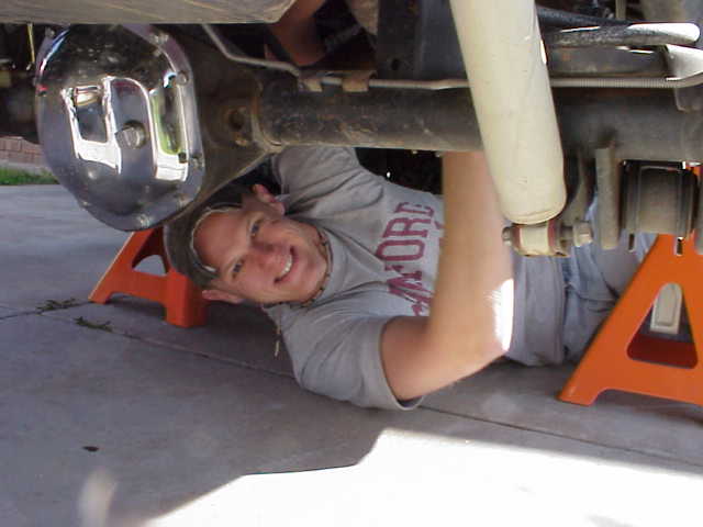
Here is a picture of Michael, a local Jeeper that lives on the other side of the valley. Michael and I met via one of the internet forums (Jeeps Unlimited) or maybe it was the local on-line club( Arizona Virtual Jeep Club). Which ever it was, Michael showed up to help Alan and I spin wrenches. I got this one of him under the rear axle taking the sway bar links off.
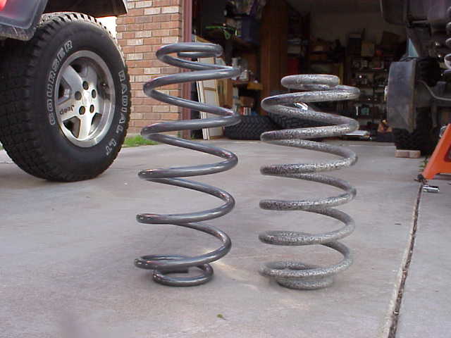
In the above picture, you can see the 4″ Procomp spring on the left and the Tera 2″ spring on the right. (and the front tire of my wife’s XJ too)
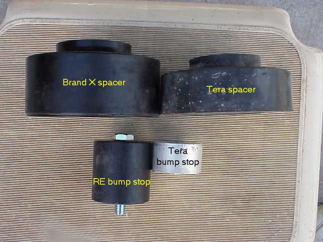
Since I was going for good height balance between the front and rear of the Jeep, I decided to use two different sized spacers. I had been running the Tera spacers shown in the above picture. These are the .75″ spacers that Tera sells and will keep your Tera springs in warrantee. Specifically, they are 1.25″ tall, but are called a .75″ spacer since you would normally pull the .5″ rubber isolator (noise deadening pad) at the top of the spring perch before you install them. I am running the Tera spacers with the front springs (with the factory isolator in place) and the Brand X spacer with the rear spring. The Brand X spacer measures 1.75″, or .5″ taller than the Tera. Since I carry a fairly good load in the rear (custom storage box) and when doing an over nighter (jerry can rack), I decided to give the rear just an extra bit of help by using a taller spacer. I removed the Tera bump stop and installed the RE bump stop in its place. I think I might be putting the Tera bump back back in (in addition to the RE) since I am going to over compress my rear springs with my current set up.
As you can see in this picture, the 2″ RE bump stop extension just protrudes through the 1.75″ spacer. As I mentioned above, I think I am going to add the Tera extension back in. If I don’t do that, I’ll get longer bump stop and insert that.
Here is a picture of the rear spring in place. You can see those new RE control arms in the picture as well. I removed the shock the following day (while finishing up the little details) when I discovered that even with the TJ sitting on the tires, the shock was about 2″ too short from reaching the lower mount.
March 25, 2001 – I installed a pair of Daystar bump stops today. I stopped the by local 4×4 shop yesterday and actually remember to get them while picking up a new set of Bestop seat covers.
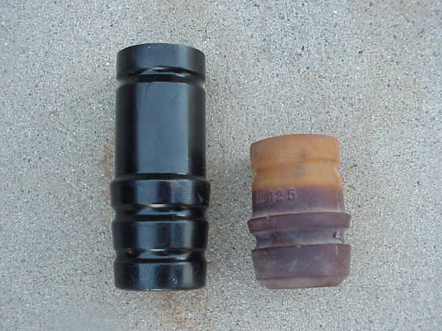
The Daystar bump stop is 2″ longer than the factory stop, as you can see in the picture above. I found that the composition of the Daystar bump stop was much harder than the factory stop. As such, pushing it into the bump stop cup was….well, I found it impossible. My final solution was to grind three flat spots on the stop, at 120 degree intervals. I took a little of the material off several times and continued until I was able to forcibly insert the bump stop into the retainer cup. Actually, I used a pry bar to persuade it to go in. This way, there won’t be any problems with it falling out on its own. So, now my 4″ spring has a 2″ bump stop in it. The RE bump stop is simply compensating for the 2″ spacer.
Round #2
The control arms were a pretty easy job in the rear, just like they were in the front. While the tires and springs were off, I slipped the floor jack under the differential housing and brought the axle up a bit so as to relieve any binding on the factory control arms. We installed the new longer sway bar links but did not tighten anything up at this time. After loosening (but not removing) all of the bolts that held both the upper and lower control arms in place, we pulled one lower at a time and replaced it with the new RE fixed lower arm. Doing it this way kept the axle from getting out of alignment and made it very easy to line the bolt holes back up. Since the factory and RE lower arms are the same length, this was pretty much a no brainer operation. The cartridge joint end was installed at the axle with the grease zirk up.
With the lower arms in place, we focused our attention on the upper arms. I got the RE adjustable upper arms so I could dial in the pinion angle for my CV drive shaft that would be installed later on that day. Neither Alan nor I had a clue as to the length that the arms should be. So, after removing one of the stock arms, we sat them down side by side and broke out the measuring stick. We decided to add .5″ to the factory length and call it good. So that we got as close as possible between the two arms, I counted the turns on the first arm that got me to the extra .5″ mark, and then ran the other arm out the same number of turns. The upper arms have the cartridge joint installed at the frame bracket (NOTE: I later changed the position of the arms and installed the bushing end at the frame bracket).
On the following day, once everything was together properly, I went through and checked the torque specs on all of the arms and made sure the jam nuts were all tight. As it turned out, our guess on the length of the upper rear arms were pretty close. We had just minor vibrations and I’ll be adjusting that out tomorrow.
Round #2
On Saturday morning, I headed over to Toyboxoffroad to pick up my first shipment of parts. Damon had given me a call earlier in the week to let me know they had arrived. In this first shipment were to be my Procomp 4″ springs and the RE rear adjustable trac bar and bracket. I had also received a set of RE fixed lowers from Brent, a Jeepin’ buddy in Tucson. He dropped them into the system earlier in the week and they arrived a couple of days ago. After retrieving the parts from the shop, I stopped back at the house to unload them. I was curious to see the springs so I had to stop and dig them out of the two boxes they were shipped in (fronts and rears).
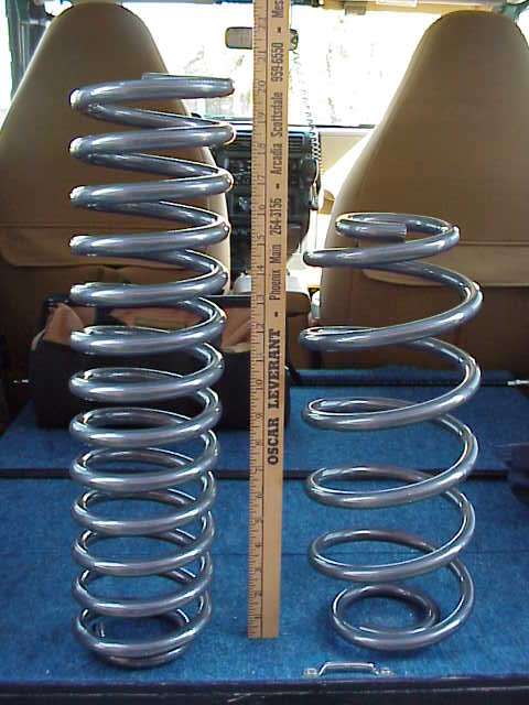
Here is a side by side of the front and rear springs. The Procomp 4″ springs, after installed are suppose to give you a 4″ lift. This is quite a bit different than the RE and Tera lifts, where there 4.5″ lifts come in usually a good 1″ higher than advertised.
Here is a pic that shows a 4.5″ RE spring on the left and my new 4″ Procomp spring on the right. Joe West, a local Phoenix area Jeeper, gave me his old RE rear springs when I was first starting out on this project. As you can see, they are just a bit shorter (now) than the Procomp spring. Joe had removed them from his TJ as they were sagging too much. I have no idea how long they are when they are brand new, but right now, they are less than 16″.
Here is the items that came in today. Those are some healthy control arms. I am looking forward to getting started on this lift….but gotta wait until the rest of the parts come in. My Tera parts for the t-case will be in next week and I should have the rest of my RE arms and the front trac bar by then.
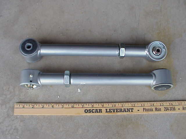
I was also able to hook up with DesertJeeper (aka., Larry) this past weekend. The above picture shows a set of RE upper adjustable control arms that I got from him. In conjunction with the RE fixed lower arms, I’ll be using these two sets to dial in the correct pinion angle on the rear axle so as to have no vibrations from the rear drive shaft.
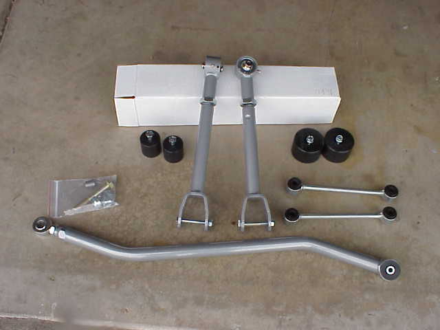
Here is the last bunch of parts that I picked up (about 10 days after the first batch of RE parts). The adjustable front trac bar with new mounting hardware, rear sway bar extension links, front and rear bump stop extensions, and adjustable front upper control arms. I drove over to Toyboxoffroad to meet Daemon, since he has been so helpful in getting my parts at a good price. I guess the benefit to meeting the boss is the nice looking t-shirt he tossed in with the parts. My wife smiled when I told her I got a new shirt…..and then proceeded to my point to my dresser and ask where I was going to put it….oh well, such is life!
Round #2
The RS-9000 shocks were sitting on the floor of the garage in their boxes. I had pulled them out the other night to get the extended and compressed measurements from them. It was time to slip them into place. The Tera shock relocators had been installed on the rear lower shock mounts and I had a pair of JKS bar pin eliminators ready to hook up with the rear shocks.
I grabbed a couple of wrenches and proceeded to get down to business. I am removing a front Doetsch Tech shock in the above photo. One nut at the top of the shock and a pair of bolts at the bottom had the shock out in no time.
Once the front shock was removed, I pulled the bar pin from it and inserted it into a front shock. I remember the fun Alan and I had when we did the first lift and had to recycle these bar pins. They were vulcanized (as best we could tell) into the factory shocks. A propane torch and a utility knife were two of the prime tools used to free them that time. In this install, I pulled them out with a pair of pliers….a much easier task this time. After the bar pin was pushed into place, the shock was installed along with its twin at the other end of the front axle.
For the rear shocks, I had purchased a pair of JKS Bar Pin Eliminators, one of which is shown above….in an exploded view. They come with both metric and SAE bolts, since the folks that built our Jeeps happened to mix and match them depending on what year you have. You’ll see in the next photo how to assemble them onto the shock.
Slide the shock onto the bar pin and slip the end block into place. You can use either a vise or a c-clamp to gently squeeze the blocks together. You need compress them just enough until the drift pin lines up with the hole in the bar pin.
Gently tap the pin flush into the block. This will lock the end block into place and keep it all together once you release the pressure holding it together. I checked the bolts that were holding in the old shocks and determined they were metric. So I tossed the other 4 bolts into the “nuts and bolts” can in Lady’s storage box for use on the trail.
Here is a picture of the JKS bar pin eliminators securely bolted into place. Not much room up there, but I had no problem getting them in place. Since these are Allen head screws, I opened the tool box to grab a 6mm Allen on a 3/8″ drive socket. Of course, Murphy got involved and I discovered that the little clip of metric Allen sockets did NOT include one for 6mm….go figure! I picked one up later at Sears and will torque them down a bit more than what I could get with a regular Allen wrench.
Round #2
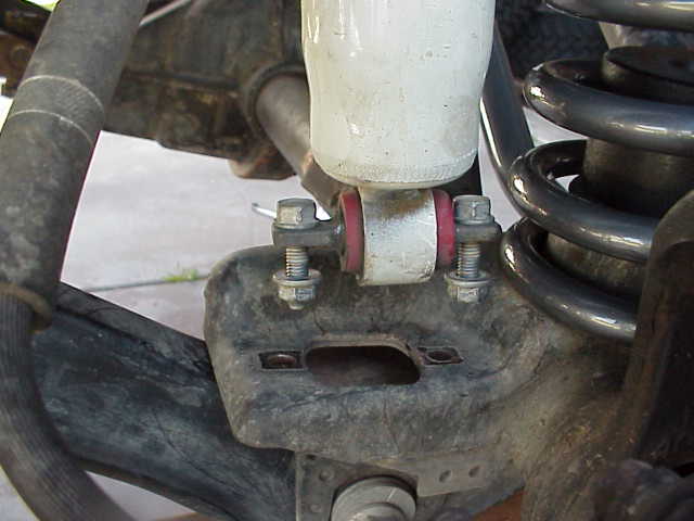
The above picture is a close up of the factory lower shock mount on my D44 rear axle. I have removed the shock and put the bolt back into place for this picture. As you can see, the area circled in yellow as been deformed over time by a few rock hits. Anyone owning a TJ knows the vulnerability of these poor shock mounts as they stick out below the axle. Since I was going to be installing a set of Tera shock relocation brackets, I had to clean up this damaged area since it would prevent the bracket from properly seating in the factory mount. I use a heavy duty punch and a 3 lb. hammer to “knock” this pushed in area of the mount back into place. A few minutes with a file resulted in a clean and smooth surface that would allow the Tera bracket to fit properly into the area.
Once the damaged area was restored to normal, the Tera bracket could be slipped into the factory bracket with a few tamps from the hammer. On the back side of the bracket, a 3/8″ grade 5 bolt screws into the bracket to hold it securely against the back of the factory bracket. You can see the tapped hole which the bolt is threaded into from the other side of the bracket.
The original shock mounting nut and bolt is used to secure the new bracket in place and a new bolt is ready to accept the business end of the shock absorber. I made sure I had the mounts in place before taking the measurements for my new shocks, as I wanted them to be as accurate as possible.
Round #2
The transfer case was next on the list of things to do. With the new springs in place, we had a couple extra inches of clearance under the vehicle to play with while doing the transfer case swap. Alan and I felt confident that we could do this in a couple of hours, which as it turned out, was correct.
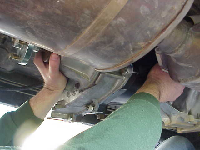
First on the plate was to remove the four nuts holding the tranny mount to the skid plate. After that, we wrestled a jack stand into place to support tranny while we unbolted the 6 bolts holding the skid plate to the frame. We had the floor jack positioned under the skid plate which made it very easy to lower down and roll out of the way.
After the skid plate was out of the way, I started on the front drive shaft. Because we wanted the maximum room available, I removed the u-joint straps at the axle end too, although this would not have been necessary. The four bolts holding the t-case end of the drive shaft in place were removed and the drive shaft was moved out of the way. We also removed the u-bolts from the D44 yoke and freed up that end of the rear drive shaft as well. I snagged a bungie cord from the back of the TJ and tied the rear drive shaft up out of harms way. Since neither Alan nor I wanted this thing to drop down onto our brain cage, I made sure it was secured well. We could have removed the t-case end of the rear drive shaft but at the time, I didn’t feel like messing with it.
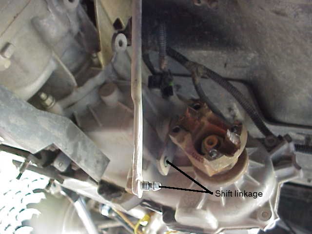
Next to be disconnected from the t-case was the vent hose, 4WD switch wiring harness, speedometer wiring harness, and the 4WD shift linkage. The t-case end of the linkage is a press fit into a little plastic socket. I was able to pop it out with the aid of a big screw driver (acting as a miniature pry bar) as evidenced in the above picture. Move it up out of the way as it has a nasty habit of hanging down right where you probably want to have you head (at least I did anyways).
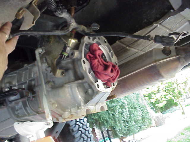
Here is a shot of the t-case with out the skid plate under it. You can see the disconnected speedometer wiring harness. With the front drive shaft out of the way, Alan and I had pretty good room under the vehicle.
OK….we were almost down to the last few nuts and bolts by now. I decided to pull the tranny mount bracket from the bottom of the transmission, as shown in the picture above. I thought one of the t-case-to-tranny mounting bolts was under there, but I was wrong. As it turned out, no harm, no foul. I was able to give the rubber mount a good once over to ensure it was not tearing or cracking. I had heard on JU that a few folks had been experiencing a broken tranny mount and the results were never good. Mine looked to be in good shape and it was returned to service after we swapped out the t-case.
With everything out of the way, we pulled the nuts off the six studs that hold the t-case to the rear of the tranny. Once the nuts were off, we started to jiggle the pull on the t-case and watched the gap widen. When we had slid the t-case rearward about 3/4″ of an inch, Alan and I both got a shoulder directly under either side of the t-case. We gave a might grunt and the t-case input shaft uncoupled from the tranny. Just as we were lowering it to the ground, about a pint of Redline MT-90 decided to run out of the tranny’s output shaft and right onto Alan’s head. There was a mad scramble to get the t-case safely onto the ground, without sacrificing any fingers, and for Alan to get out from under the spewing stream of synthetic gear oil.
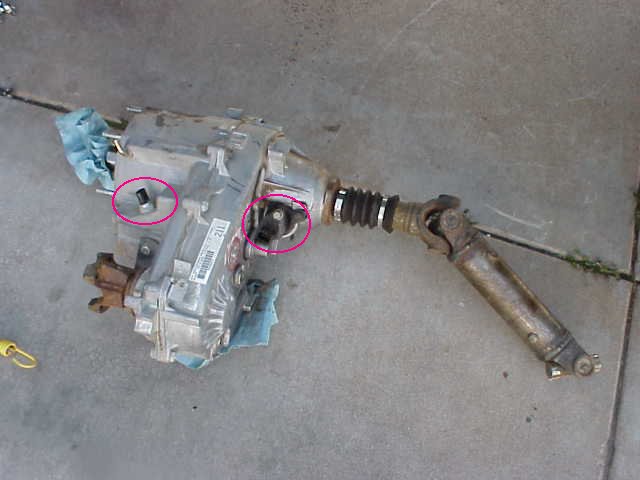
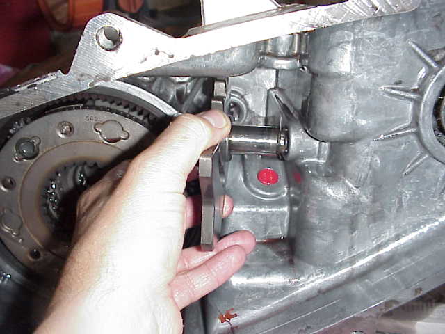
With the t-case safely on the ground, we slid it out from under the Jeep. I got Alan a handful of paper towels and a towel. While he proceeded to remove the gear oil from his hair, I removed the 4WD switch and the speedometer housing (two items above circled in red) from the t-case since these have to be transplanted to the 4:1 equipped unit that we were installing.
Round #2
With a clean shop rag tucked into the weeping tranny, I snapped this picture so you could get an idea of what the manual tranny looks like without the t-case attached. After the oil bath, Alan and I realized that we were letting the tranny sag a little too much (didn’t have the jack stand up high enough) which is what caused the loss of MT-90. I teased Alan about getting some of the “best synthetic gear lube that money can buy” in his hair. Heck, some folks go to fancy spas to get this kind of oil treatment. I guess we can be grateful that it was not hot!
Alan’s hair was about as good as it was going to get and I had successfully migrated the parts over to the new t-case. Now we had to come up with a plan on how to hoist the new beast into position. Once again, it was Alan to the rescue, this time as “Alan, the human transfer case hoist”. Alan positioned himself squarely under the tranny area. Now you have to realize that what happened next could only be accomplished because of the years of beer drinking that Alan has done. Alan rolled over on his side and together, we rolled the t-case onto him as he rolled onto his back. At this point, the human transfer case hoist was ready to raise the t-case into position. Alan took an extra deep breath and proceeded to expand his stomach (remember, the one that has had years and years of beer poured through it) until the t-case was at the proper height. With him steadying it, I guided the t-case forward while clocking it a bit to get the 6 studs to engage the tranny flange. With a quick spin of the output shaft which got the splines engaged properly, we pushed the t-case home and securely up against the rear of the tranny. I grabbed a couple of nuts to temporarily secure it in place while Alan let out that extra big breath he was holding.
We finished up getting the remaining nuts on the studs and tightened them. Since it was impossible to get a torque wrench on them, I gave it my best guess (you know, calibrated torque wrench wrist) and we called it good.
From there, we just retraced our steps and started putting everything back together in the opposite order we took it apart in. Heck, we were done with the hard part! Everything after this was a down hill coast.
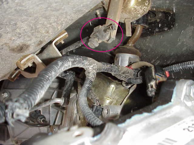
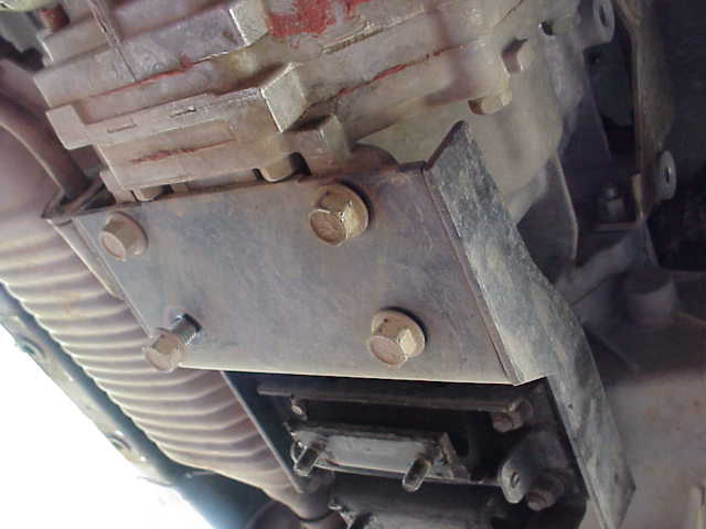
Here is the t-case shift linkage adjustment point that you may or may not need to adjust depending on what all you did. I installed the 2LO with my 4:1 but from what I can tell so far, I am dropping into 2LO just fine, without having to have made any adjustments. Your mileage may vary!
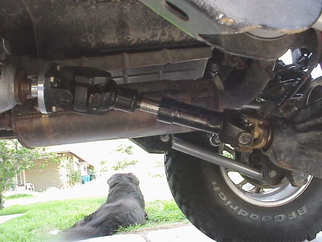
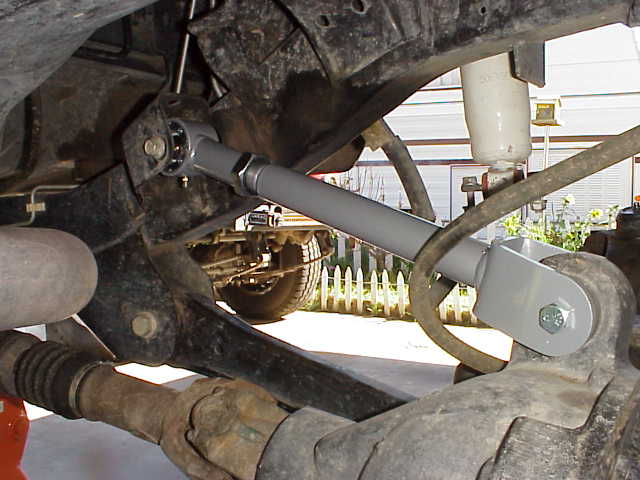
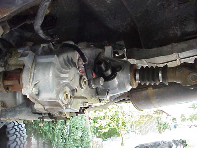
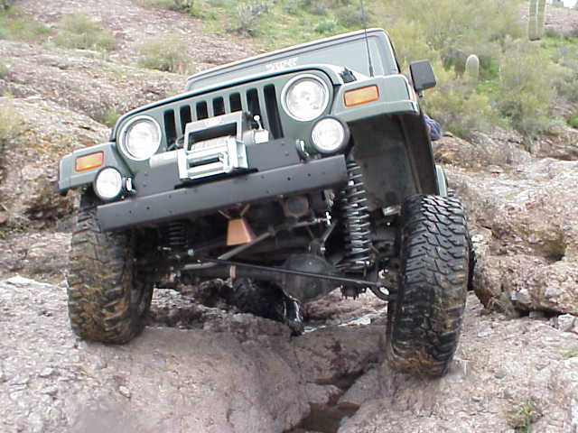
Here is the business end of the Tera 4:1, the RE SYE and CV drive shaft. (and my trusty old dog, keeping an eye on the neighborhood) I had not adjusted the pinion angle when this photo was taken, so don’t judge anything based on what you see here.
Round #2
The info on this page is just a summary of various numbers and measurements that I took while working on the TJ. They are only provided as a comparison point if you get to wondering how long something might be.
Shock Mount Measurements
| Front axle | Extended |
25 1/4“ |
| Static |
21 3/4“ |
|
| Compressed |
17 1/2“ |
|
| Rear axle | Extended |
24″ |
|
|
Static |
20″ |
|
|
Compressed (will cause coil bind) |
14″ |
Shock Absorber Measurements
| Front axle | Extended | 26″ |
| Rancho RS-9017 | Compressed | 16″ |
| Rear axle | Extended | 26″ |
| Rancho RS-9112 | Compressed | 16″ |
Update 07/26/2001
Since the above measurements were taken, I replaced the front stock lower control arms with a pair of RE adjustables. Where as the factory arms would bind in the control arm bracket and thus limit droop, that is no longer the case with this new configuration. The limiting factor now is my RS-9000 front shocks. I took the opportunity to “ramp” the TJ on my favorite rock on Raw Deal, right after I had put the new arms in place. I found that the axle will droop more than the shock will allow. However, I must also state that at configuration, the spring is starting to get loose in the spring perch so there is very little pressure being applied by now extended spring. Given all of the variables involved, I think I am satisfied with the shock length, axle droop, etc. I am sure it could be “tweaked” for a bit more suspension performance, but I do not need it nor do I care to pay for it either.
Measurements to the Ground
| Bottom of factory bumper (front) | 26 1/8“ |
| Bottom of frame under door | 20 5/8“ |
| Bottom of rock crawler bumper (rear) | 23″ |
| Bottom of 35″ spare tire | 32″ |
Front End Alignment –
Lady has been on the trail twice now, as I write this, since the lift was installed. She has had a chance to flex the springs a bit and I am assuming that everything has gotten into its “settled in” position. I had made an appointment last week with the alignment shop down the road and stopped in this morning to have them check the front end out.
I spoke with the tech that would be doing the work. Told him the lift was about a month old, wanted the front end checked, the handling was rather twitchy on the highway (I suspected not enough positive caster)….and told him the torque specs for the adjustable control arms.
The work took right at 3 hours. Lady was on the alignment ramp three different times (the initial checkout and twice to check the control arm adjustments).
As I had suspected, the caster was quite a bit off. The tech informed me that Lady was sitting at 1.5� positive caster. The TJ factory specs is 7� +/- 1�. I knew there was no way we were going to get to those numbers. I was sitting at about 5.5� when I had the Tera lift on. The toe-in was almost 1″ off as well. I was not expecting this, but since I was there for an alignment, it cost no more to have this fixed as well.
We discussed my options on the caster problem. The shop has a policy concerning after market parts (ie., lift kits)…..you pay more if you want them to adjust a lift Jeep. At first I decided to do it myself, but that would require scheduling yet another visit to the shop. The tech offered to check it for free if I did the work (he would adjust the toe-in and center my steering wheel) and wanted to bring it back in. After thinking it over, I decided that my bones were too tired to play “guess the caster angle” so I told them to do the work.
Lady was taken off of the alignment rack and moved over to another lift where the lesser techs (I think they have some kind of pecking order because they were a lot dirtier than the guy that I was talking to) worked on the upper arms. Some time later, an opening on one of the two racks was caught and Lady was once again hoisted up and the alignment hardware attached to all four rims.
The tech reported that they had shortened the upper RE arms by 2 1/2 full turns. It brought the caster up to about 2.5�. There was 2 or 3 threads showing on the arms and we had the factory adjustment that could be tweaked up as well. They took it off the alignment rack and sent Lady back to the dirty guys.
Once again she returned and was put on the alignment rack and fitting with the alignment fixtures. (She reminded me of Forrest Gump with his leg braces!) The tech cranked the factory caster cams to their most positive position and locked it back down (that reminds me, I need to torque all of those front arms again). The readout on the alignment computer showed Lady right at 4.0� positive caster. That was as good as it was going to get. Now the only question left in my mind was the front pinion angle…..would be cause vibrations or not?
So….I did a number of drives around town today while attempting to find a shipping store to UPS my old lift and shocks. While driving around, I noticed a bit more vibration than I had prior to the alignment. OK….so I got a much improved steering configuration (it was no longer twitchy at speed), but I got a little front drive shaft vibration.
While writing this, I decided I would play with the factory caster cam bolt (lower control arm, axle end). This was the one that the tech cranked to the maximum positive position. Since it was rather easy to see which way it was at the max position, I opted to back it off two alignment marks….going towards the 12 o’clock position. I snugged the bolts back to spec (I still had Alan’s torque wrench from Sunday morning’s episode) and took Lady for a ride. It was a bit better in the vibration department (still could feel them) and the steering still felt just fine.
I decided yet another adjustment was in order, so I decreased the positive caster to the 12 o’clock position (which is where it was when I took it to the shop this morning, albeit, the control arms were in a much different configuration). I torqued the bolts down one more time, put the tools away, and took it for another ride.
Not too bad….the steering still feels good (I get good return to center after turning a corner) and the vibes seem no worse than when I woke up this morning.
I don’t know how the exact amount of adjustment the factory cam bolts have, but the tech at the alignment shop thought it was in the neighborhood of +/- .5�. So, if this is somewhere near correct, I have my caster sitting at about 3.5� positive, give or take a little bit.
I think that is where it is going to stay. I may get adjustable front lower arms some day, but then again, maybe I won’t. If I have good handling and the front drive shaft is not giving me trouble, life isn’t so bad now, is it?.
Round #2
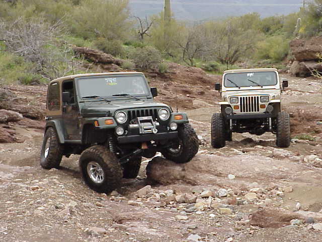
Phone calls and e-mails were exchanged on Saturday night in anticipation for a Sunday checkout run. We were unsure of the weather but I was told we were going, rain or shine. It was decided that DesertJeeper (aka., Larry) would be riding shotgun in Lady and Blatant (aka., Dion) would be wheelin’ his YJ, which too had just finished its build up project. Dion put a Ford 8.8″ rear axle under his YJ and installed SOA with 36″ Swampers. We would both be taking some hard looks at how the trucks were flexing on the trail.
My first concern was the clearance up front. I was hoping that the 6″ suspension and 1″ body lifts would be enough to keep the 35″ MT/Rs out of the flares. I was pretty sure I would still need to be adding some more bump stop extension on the rear axle based on flexing things up in the driveway with the floor jack under the rear axle.
We entered the trail and I climbed up and over a few boulders that litter the start of the trail. So far, so good. No bad noises, no snaps or pops….keeping the fingers crossed. I slipped the Tera equipped t-case into 2LO and turned a tight corner. Oh yes….I like that feeling. I also quickly discovered that I can shift back and forth between 4LO and 2LO with no need to stop, clutch in, etc. (just like shift between 2HI and 4HI) There was some gear wine when I went into LO range, but that was to be expected. The Tera literature said it would take a while to get the gears broke in and they would become less noticeable with more use.
We came to an appropriate rock and I let Lady put her front tire up on it…..nothing too major, just enough to flex things a bit. I hopped out (not too smart….the driver’s door was sitting directly over a low spot adjacent to the rock I was parked on…what a drop….and worse yet, what a climb to get back in!). I was interested to see how the front tire was stuffing into the fender well.
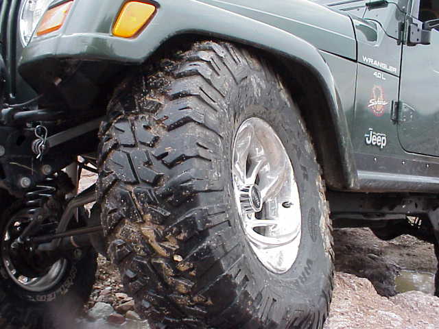
I was delighted to see that I had almost a 1/4″ of clearance at the closest part of the flare! AND…..the Procomp coil was compressed down to the bump stops. That took care of that question. My choice of bump stop length for the front was right on the money. Any less and the tire would have been in the flare…any more and I would have been wasting good flex potential.
The opposite corner rear tire was a slightly different matter. It was just beginning to lightly touch the back edge of the rear flare. I stuck my head underneath to get a look at the springs. It was still better than an inch, closer to two, before the bump stops would limit the travel. I had noticed, while taking measurements for the compressed length, that I was going to need some more bump stop here to prevent over compression of the spring. The spring will probably stop from coil bind first, but I do not wish for that to happen. Make note to self….get some more bump stop for the rear springs.
While we were driving to the trail, I had told DesertJeeper that I was going to take it easy today. Nothing too difficult…this was a run to check out the wrenching I had done during the previous two weeks. Well, that was to change after we went over the Great Divide. It went without a hitch, as Larry spotted me over it. The MT/Rs grabbed those rocks like glue, even though we were running a wet trail.
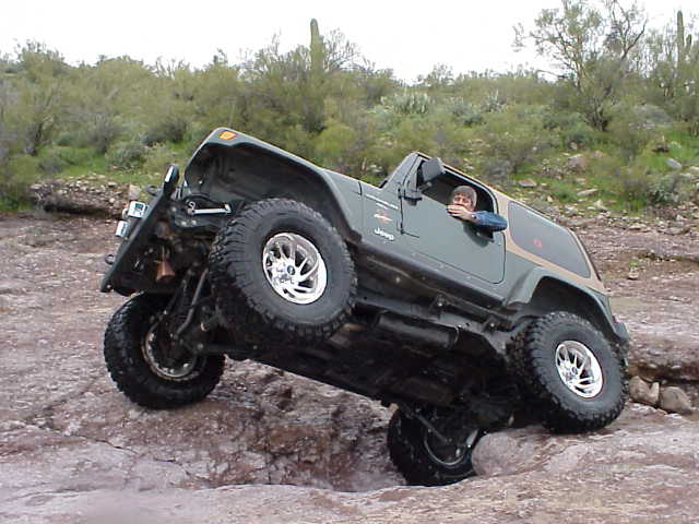
So, with Blatant out of the way, I put Lady into the Air Hole to see how it felt. I had been through this obstacle a few times over the past couple of months and I’ll say that even though I was sporting a bigger lift and tires, Lady felt very stable as she went clawing for air. The biggest change I noticed was that the control was ever so much better. The Tera 4:1 gears in the transfer case allowed a much slower crawl through this obstacle. I knew right then and there that those reduction gears were money well spent.
Round #2
We drove a bit further down Lower Raw Deal and I found a boulder off to the side of the wash that would afford me another chance to flex, this time a bit more than the last (I was hoping anyway). It went well this time too. The front brake line (passenger side) is about maxed out, but I think I was in control arm bind at that point too. It was not tight like a banjo string, but I would not want it to get any more tension on it. I will either lower the frame mounted bracket another inch or slip in a longer set of stock YJ lines. The spring could be wiggled by hand on the pedestal, although it was not flopping around.
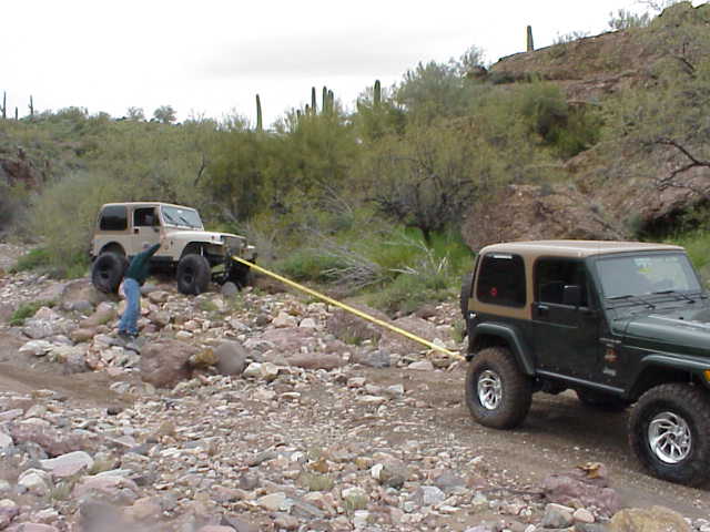
By this time, Blatant was looking for more and more challenging obstacles. We came around a bend in the wash and he remembered this pair of boulders up ahead that he had wanted to tackle for a long time. Well, to make a long story short, you can see that he found this to be just a bit more than he could handle today. The driver’s side frame rail got hung up on a rock and the driver’s side rear tire just couldn’t get any traction to climb up and over. After rocking the YJ a bit and finding that did not help, I got the strap out from behind the seat and Lady hooked up to the YJ. Bill got us positioned (in the photo above) and then moved out of harms way while I dug a couple of holes in the wash and pulled the YJ off the rocks. Oh well….just another page in the life of a TJ owner! (I hope Blatant gets around to reading this page!)
We finished up Lower Raw Deal and broke for lunch. I quickly inhaled the lunch that Donna had made for me, and swapped a few build up stories and talked Jeep for a while. It was a little bit after noon and we decided to do Upper Raw Deal since we had the time and neither Blatant nor I had ran it before.
———————————–
Goodyear MT/R comments:
I guess this is a pretty good place to comment about the Goodyear MT/R 35″ tires I’ve now put a couple of trail hours on. I was totally impressed with them. Sure, they slipped in a couple of places, but then again we were running a wet trail. Everything was either wet or mud or more wet….take your pick.
I aired the tires down to 10.5 lbs of pressure, per my 15 psi gauge, at the start of the trail. DesertJeeper and I had been keeping an eye on the tires. We were both amazed at how well the tires wrapped around the rocks and ledges I let Lady crawl over. Even Blatant (who had been running 33″ MT/Rs on his YJ before the SOA) comment that they seem to have a tremendous amount of flex in the side wall area. You could see the sidewalls actually wrinkle while engulfing a rock. I realize that having a tire that stands 3″ taller than my previous tires certainly helps, but I watched those tires climb up and over rocks and ledges I would not have though possible….at least not while everything was soaking wet. At one point, on the last obstacle of Upper Raw Deal, we temporarily lost a bead on the right rear tire. DesertJeeper and I both distinctly heard the air escaping on no less than two occasions. We thought we had initially lost a valve stem, but on closer inspection, the stem was in perfect condition. It looked like we had gotten the rim into the rock, but I think the big old bulge helped me keep my rim in OK shape.
All I can say is that I really like the tires so far. If today’s performance is an indicator of what is to come, I am going to be very happy with the results. I look forward to seeing their performance at Moab in a month. I am hoping they hook up on the slick rock as well as they did on the composite rock that is so common on Raw Deal.
———————————–
OK…back to the rest of the trail run….what were we doing….Oh yeah, checking out the flex and seeing just how well it was working (it was easy to forget we were on a fact finding mission rather than just a Sunday romp down a fun wash). Upper Raw Deal is pretty short, but has a couple of interesting obstacles in it. I did the first and last ones just fine, but got out sync on the middle one (that was the one I lost the bead on for a short bit).
A little more flexing was done coming out of this obstacles on the upper trail. You can see that the tires are just plain wet. This is almost solid bed rock in his part of the trail and the water pools up, sometimes reaching 3′ in spots. Dropping into one of those keeps you on your toes, not too mention that it is cold!. Again, the Tera 4:1 let me crawl through these spots with little problem.
I am almost through the last obstacle on upper at this point. Although the camera is too close to see why, DesertJeeper caught me taking the correct line for this obstacle. The side lugs on the front MT/R are used to climb up the rock in order to clear the boulders sitting just ahead of the Jeep (and not in view of the camera). It took me a couple of times to get lined up on this one correctly. Just the tiniest bit of momentum and the right approach angle is needed to get the left side to track up on the rock.
We headed back to the main gravel road and stopped for a bit. I let Blatant talk me into running the first couple of obstacles on the Terminator trail. He wanted to get back into a bit and then walk a spur trail that cuts off of it, called Anaconda (nasty, nasty trail). You won’t see Lady on that one for a long time. To much body damage on that one, assuming you get through. You should have seen the paint chips on the ground and scraped into the rocks. OUCH!
Round #2
I got home today to find a fairly heavy box sitting on my front patio (UPS was hoping someone would steal about $1K worth of parts maybe?). Not too sure about that but luckily it was still there when I got home.
The box was from Supplee 4WD Enterprises, Inc., a small 4×4 shop in Moore, OK. (405) 799-8977 Bob Supplee is a great guy and I have purchased a number of Lady’s parts from him in previous years. Every time I call his shop, it is kind of like running into your cousin at the family reunion. We catch up on what each other has been doing, update each other about mutual friends…..well, you know what I mean. He gave me a great deal on the Tera 4:1 and the 2LO kits for my NP-231 transfer case. At this time, Bob does not have a web site, so don’t go looking for it. Call around, get your prices, and then call Bob to see how much you will be saving and then order your parts! It works for me.
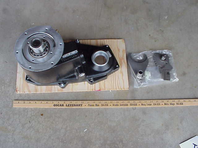
The above photo shows the Tera 4:1 as it came out of the shipping box, bolted to the plywood backing plate. The Tera 2LO kit is on the right. Not much to it. I’ll be getting with a friend this weekend and working on the spare transfer case. I really need to have it completed before I start my lift. Once those Procomp springs are in place on Lady, she won’t be rolling anywhere until the new CV drive shaft is in place, and that means the spare t-case with the SYE has to be in place too. FYI, the other parts for the 4:1 kit are stashed inside the housing. You will find them when you remove the two bolts that is holding it to the backing plate.
Round #2
We started about 8:30 AM on a Saturday. I had loaded the spare t-case into the back of the TJ along with the Tera 4:1 and 2LO kits. I had a Thermos full of hot coffee and a couple of bucks in my pocket in case we needed something at the last minute. Before I got to Alan’s house (a very good friend that volunteered his garage bench and the necessary pile of tools), I stopped at AutoZone to get some carb cleaner. I wanted something to clean the residue off of the sealing surfaces when we started to RTV the parts back together. Mr. Murphy (of the infamous Murphy’s Law) would strike only once during the t-case buildup, forcing me to return to AutoZone to pick up a tube of Permatex RTV sealant (the tube Tera was suppose to include in the 4:1 kit was missing…..or their parts list is out of date).
Alan had cleaned off the necessary bench space prior to my arrival. When I pulled up into his driveway, he greeted me with the garage door open, tool boxes unlocked, and a generous layer of newspaper spread across the bench. I open the back of the TJ and carried the t-case to the bench. I grabbed the Tera 4:1 case and set it near by, after I removed the wooden backing plate from it. With instructions in hand, we fired up the compressor and got to work.
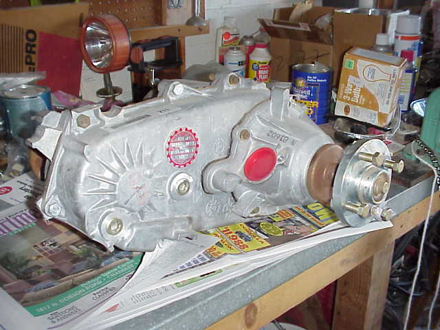
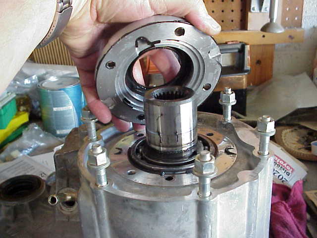
Here is my spare t-case with the RE SYE and CV drive shaft mounting flange sitting on the work bench. I bought the t-case with the CV drive shaft from a local Jeeper (Joe West) a couple of months ago. When my stock t-case is removed from Lady, it will be going back to Joe as a core deposit, so to speak. Basically, I bought the RE SYE which just happened to be installed on his t-case, so he gets mine back to even things out.
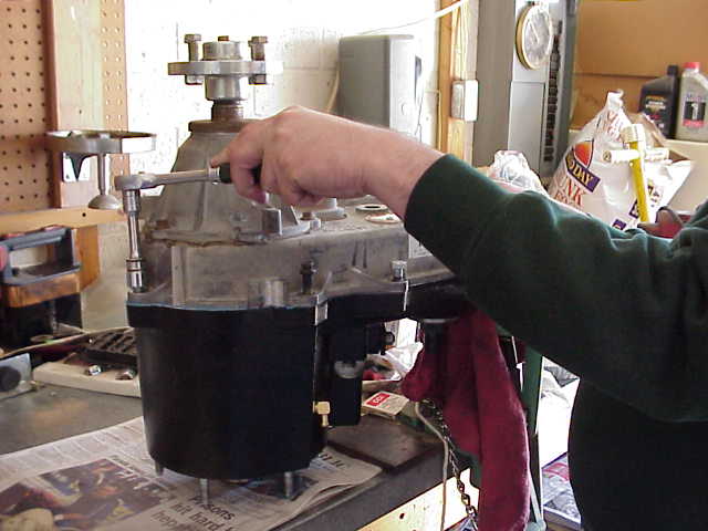
The first step was to drain the ATF from the t-case. I grabbed my 10mm allen socket and put it on a 3/8″ ratchet, but couldn’t budge the fill or drain plugs. Alan handed me a 3/8″ impact wrench and was I able to remove the drain plug. We finally had to switch to the 1/2″ impact wrench to get the fill plug removed. There was no way anything was leaking past those plugs! With the plugs loosened, I set the t-case on the oil catch pan to let the fluid drain out. Be sure to tip the t-case all around and get as much out as you can….then try to get some more out. If you don’t, you’ll have a pretty good ATF slick on your bench when you finally separate the case sections.
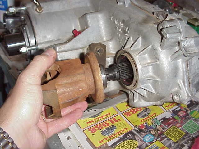
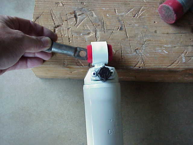
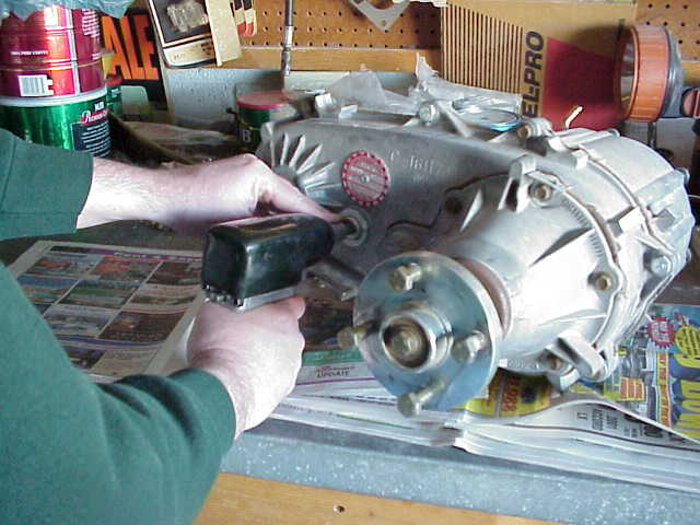
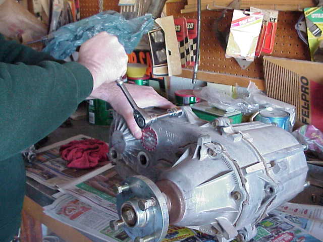
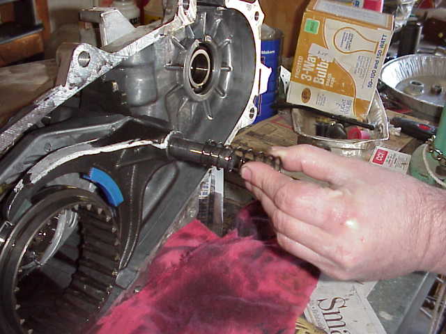
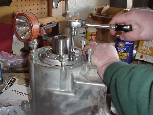
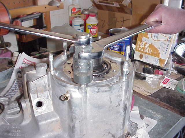
Since the 1/2″ impact wrench was handy, we slipped a 1 1/8″ deep well impact socket on it and proceeded to remove the front yoke nut. The torque spec on the yoke nut is about 110 ft. lbs. and I wasn’t going to bust any knuckles this early in the project trying to get it off with a ratchet. You can see me removing the yoke from the front output shaft in the picture above. I was expecting to need a gear puller to get it off, but was pleasantly surprised to find I could remove it by hand with just a bit of effort.
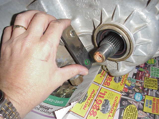
The instructions say to move the transfer case range lever all the way rearward, to the four wheel low position. In the picture above, I am pushing the lever all the way back. You can verify you have it in the right position but turning the input shaft and noting that both the rear and front output shafts turn at a reduced rate (about 2.73:1….ie., low range).
Round #2
The next step is to remove the bolts attaching the rear case to the front case. As the instructions say, be sure to keep these bolts as you will be using them to bolt the case halves back together. I am not sure why DC did it (it is in the FSM though), but they put used one spline head bolt in with the rest of the hex head bolts that hold the t-case together. It is just to the right of the 15mm one that Alan is taking out. I cheated and used a 12 point socket on it and it took it out just fine. Later on, I told Alan the FSM said it was a spline and he told me he had spline wrenches. Oh well, what can I say….maybe the reason will become clear once I put the t-case in Lady.
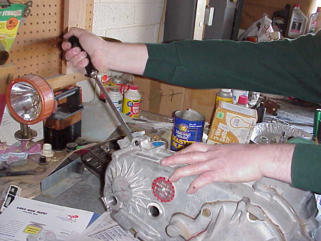
After the bolts were removed, we grabbed a pair of the biggest screwdrivers Alan had. There are two slots, one on each end of the t-case, where you can inset the blade and pry the case apart without scratching up the sealing surface. Use the biggest screwdriver you can fit into the slot. Here is Alan putting the lean on of the slots.
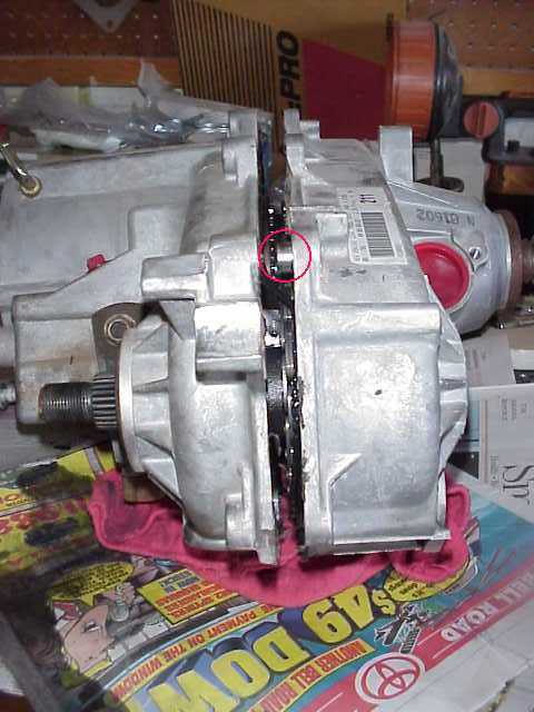
With a bit of tenacity, we were able to separate the front and rear halves from each other, as shown above. The RTV will work against you while doing this, but it can be overcome without too much effort. Note that there are two metallic alignments dowels that you need to keep track of. An alignment dowel is a sleeve that fits into a bolt hole and causes the opposite case to align itself when you are pushing them back together. You need to make sure they remain in the rear case half (or more them to it when you get the cases separated) since they too need to be used upon assembly. One of the dowels are circled in red in the above picture. You will be able to clearly see them once the cases are completely apart.
Continue to work the cases apart from each other. Take your time, being careful not to get those big screwdrivers onto the sealing surfaces. You don’t want to gouge them up and risk having a fluid leak after you put everything back together. It requires a bit of pushing, pulling, prying, and shaking. Unfortunately, I don’t remember what order all of that occurred in so you are going to have to experiment a bit until you get them apart. Just take it easy so you don’t end up with a bench full of parts all scrambled up and you are thinking “Now how did those things all fit back together?”
Round #2
I should comment here that when we separated the case halves, not everything ended up staying in the “correct” half of the cases. Well, I should say they didn’t quite look like the did in the instructions. This didn’t really make much of a difference, since I replaced much of the parts that were on the wrong side, so to speak. These were the replacement parts for the 2LO kit. I just thought I would comment about it and tell you not to worry too much. Take you time, get acquainted with what parts are where, how they slide back and forth on each other, etc. After you do, you should be able to recognize which parts engage to give you 4 wheel drive, when 4LO is engaged, etc…..you know, a quick self-taught course on “Transfer Case 101”.
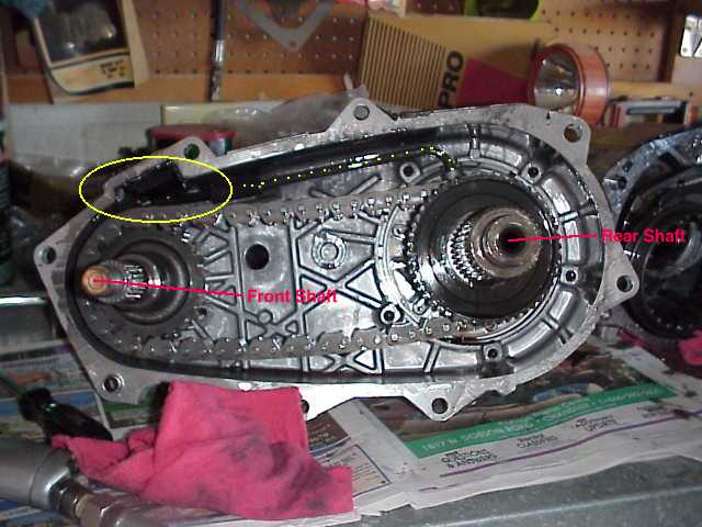
Here is the back case section. You can see the big ol’ chain drive. The oil pump is located across the top of the case. The pickup screen is circled in yellow and a string of little yellow dots trace the oil tube. Although not mentioned in the instructions, I cleaned the residue from the pickup screen. It slides out of a grooved recess in the housing. Don’t get too carried away while cleaning it. I didn’t want to pull the other end of the tube loose. My screen had some small metal filings on it and these where easily cleaned off with some carb cleaner. The front and rear shafts are also labeled in the above picture.
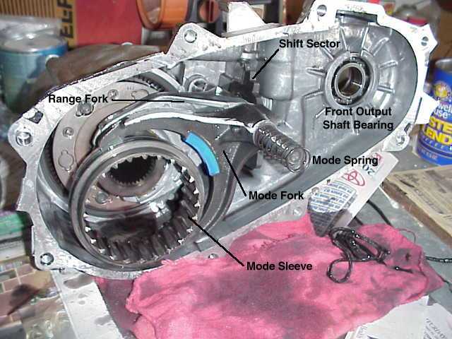
The above picture shows the front case which we’ll be discarding once all of the parts are stripped from it. The mode spring, mode fork, and mode sleeve are all used again, along with the front output shaft bearing and and a few other parts that I’ll get to. After removing the mode spring, carefully pull the mode fork towards you while holding onto the mode sleeve. The shift rail will come out also, as it is attached to the mode fork. The mode sleeve can easily slip right out of the fork and you don’t want to drop it and crack it. Because my chain and shafts stayed in the rear case (unlike the pictures in the instructions), I did not have to bother with removing them from the front case as covered in steps 7, 8, and 9 of the instructions.
You can also see the shift sector and the range fork in the above picture. The shift sector is turned by the shift lever (attached to your 4 wheel drive shifter). It works on a series of cams and a slotted part that causes the mode fork (2WD or 4WD) and the range fork (HI or LO) to move into position at the appropriate times when you change the position of your shifter.
OK….on with the show. Alan removes the mode spring. Set it aside as you will be using it when you assemble the t-case. (Did you see how clean this guy’s hand is? OK…you guessed it, I did most of the work and when I had to take the pictures, I used Alan as the prop for the photos!)
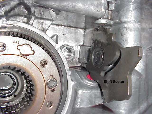
After you remove the range and mode forks, along with the mode sleeve, you can get a good look at the shift sector. The red area below the shift sector is a plastic plug and is in the hole where the 4WD indicator switch is located. My switch will be switched when I pull the t-case from Lady and install this one. You can clearly see the slot that is cut into the shift sector. This is what controls the range fork’s movement. The pointing tips at the top of the shift sector are the detent positions that you feel as you move your 4WD shifter in the cab.
Since I am installing the Tera 2LO kit, I will be discard this shift sector and replacing it with a new one that has a 5th position for the 2LO range.
Round #2
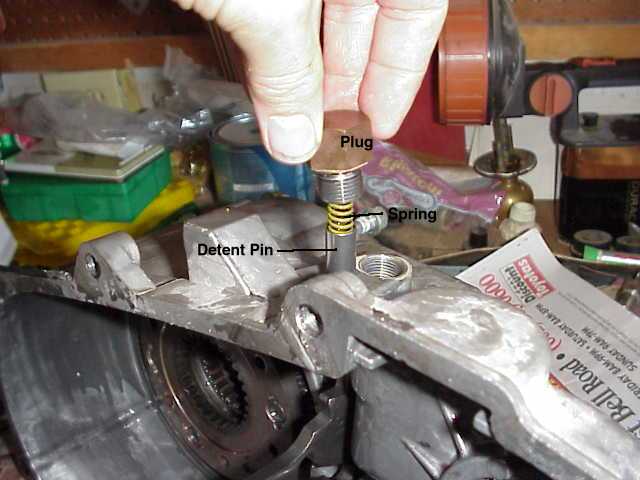
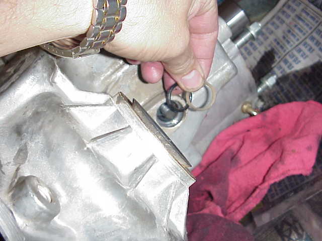
The detent pin must be removed. The detent pin is what engages the notches on top of the shift sector and keeps everything locked into the right position. In the above picture, I am holding the plug, spring, and detent pin next to the threaded hole it was just removed from.
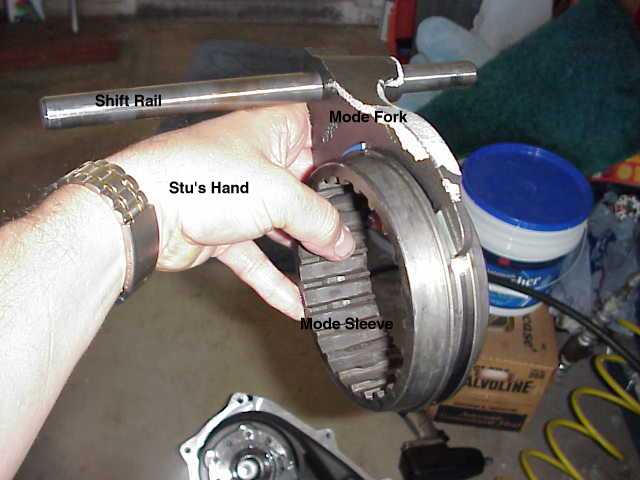
The above picture is a good view of the mode fork, shift rail, and the mode sleeve. When you look at the inside workings of the t-case, you should be able to see how the mode sleeve travels back and forth and engages the gear that causes the front output shaft to turn. Again, be careful to keep control of that mode sleeve as it easily slips out of the mode fork.
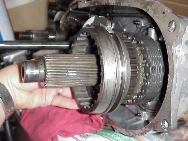
I included the above picture just to provide another view of how things fit together. In this show, I have the mode sleeve almost completely removed from the gear on which is mates. The gear with large gaps between the teeth (just in front of the drive chain) is the gear that drives the front output shaft. When the mode sleeve travels back towards the chain, it engages that gear and locks it with the gear just in front of it. At that point, you are in 4WD. The position of the range fork will determine if you are in HI or LO range.
In this picture, I have removed the shift lever from the end of the shift sector shaft. Set it aside as you will be using it when you put everything back together.
Gently push the shift sector shaft into the housing a little ways. There is a nylon bushing and an 0-ring that you must remove from the end of the hole. Clean these off and put them with the other parts that will be going into the new rear case. Remember that the o-ring goes in first and then the nylon bushing.
From the inside of the case, gently pull the shift sector out of the shaft hole. You might have to wiggle it around a bit to get it to clear everything, but it will come out without much trouble. Hang in there….you are almost done scavenging the parts from the old rear case. Just a couple more parts and you will be officially half way done with the project!
Round #2
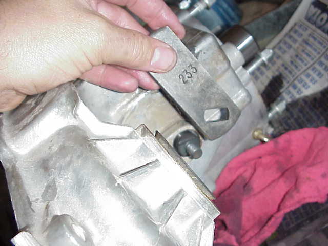
OK….time for an easy one. We now need to remove the front bearing retainer cap.
Here is Alan applying a little bit of leverage to one of the four bolts that hold the retainer cap on. It is pretty easy to take these 4 botls out, piece of cake!
Once the bolts are removed, you can again use that big screwdriver to pry the cap off of the housing. Yep, it has some RTV sealant on it so it will take a little bit of effort, but nothing you can’t handle by now. You made it this far….heck, you are darn near a t-case veteran! Somewhere along the line you need to clean the RTV residue off of the retainer cap. If you want, pull up a stool, take a load off of your feet, and clean the cap. Be careful not to scratch up the sealing surfaces. Also one thing to remember when putting this cap on the new case….those bolt holes are not equally spaced. There is but one way that the holes line up. Be sure you have them lined up before you squish the RTV covered plate into place.
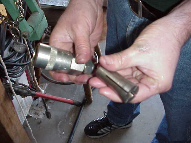
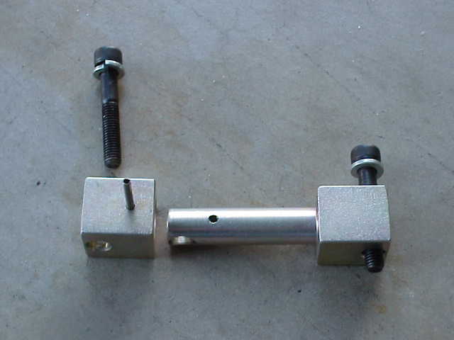
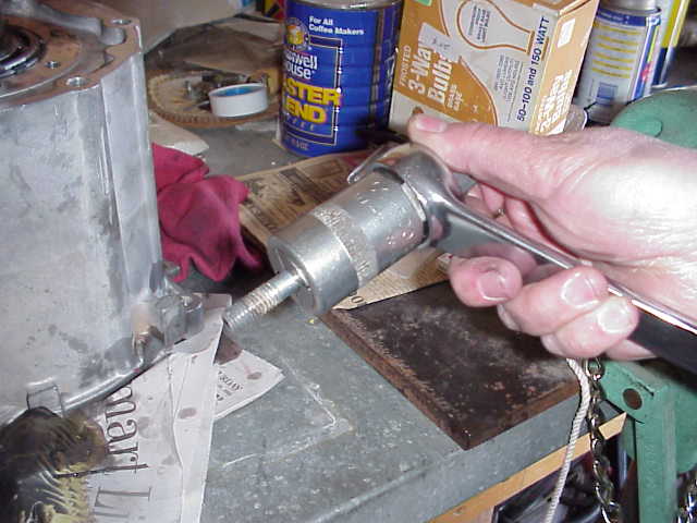
So….you are probably wondering what the heck those two things are that Alan is holding? Well, it is his handy-dandy stud puller. Up until this project, I didn’t even know that such a tool existed. After this project, I hope I never have to pull any studs again without having one of this little beauties. So, how does it work? The piece in Alan’s left hand is a tapered collet that matches a specific size bolt/thread pattern. Just in case you were wondering, the studs in the rear housing (the ones that attach the transfer case to the tranny) are 3/8″. The thread that goes into the t-case is coarse thread, and the thread that sticks out (the tranny end of the stud) is 24 pitch fine. The collet is loosely inserted into the outer shell (the piece in his right hand) and the adjustment nut at the top is turned to take the slack out of the setup. It is then threaded down over the stud. Once you have engaged as much of the stud’s threads as possible (all of them in the case of the studs we are talking about here), you tighten up the adjustment nut. This pulls the collet into the outer shell and forces the collet to tightly grip the stud (and I mean it really grips that stud big time!). Then, you take a 1 1/8″ open end wrench and turn the outer shell, which in turn causes the the tightly squeezed collet and the stud to all turn as a single unit. Iti is as easy as that. Let’s take a look.
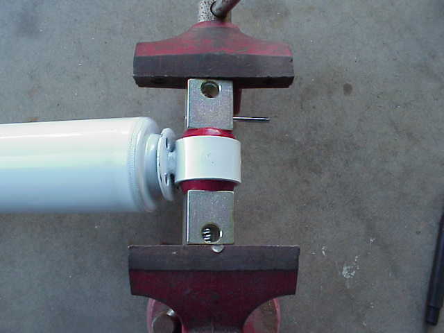
In the above photo, the collet has already been screwed down onto the thread. We are tightening the adjustment nut at the top of the outer shell. To do this, we used a 7/8″ wrench on the nut and held the shell in place with the other wrench. Remove the adjustment nut wrench and start unscrewing the stud using the wrench on the outer shell.
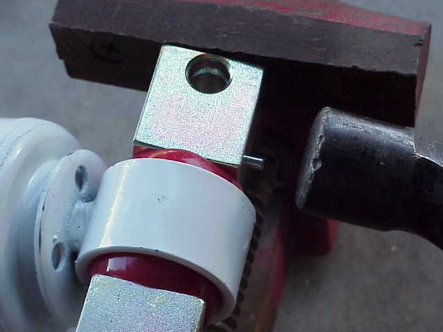
There you go…..easy as that. The thread comes right out of the case housing, just as good as the day it was installed. You then loosen up the adjustment nut a couple of turns and tap on it a couple of times which causes the collet to slide out of the tapered shell. You then unscrew the stud form the collet with just your fingers. OR…..you can use the method offered in the instructions which is to double nut the stud and then unscrew it with a wrench on the lower nut. This will certainly work, but I guarantee you it won’t be as easy as using a Snap-On stud puller.
Round #2
Now that the studs are removed (by whatever method you had available to you), it is time to salvage the front output shaft bearing from the housing.
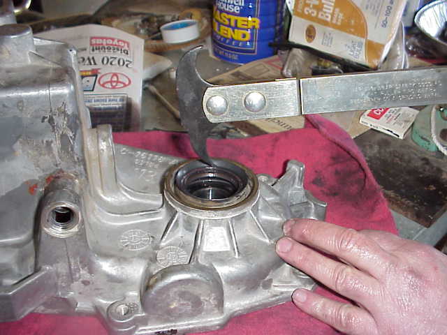
Of course, Alan wanders over to the tool chest and comes out with a seal puller. Now I knew there was such a tool, but I had never seen one. Today was my lucky day, as Alan proudly presented me with the puller and told me to have a good time with it. All it does it hook the underside of the seal and you leverage it out of the housing. The picture above has Alan pretending he is going to pull the seal, but once again, he was just posing for me to take the picture. Oh well…..

The picture above shows the seal just coming out of the housing. I was quite impressed at how nicely the seal remained in one piece. I think I could actually reuse it if I had to. Luckily, Tera includes a replacement seal with the 4:1 kit so you can pretty much mangle this one to pieces, if you need to. Just be careful not to bang up the snap ring or the bearing which are both located below the seal.
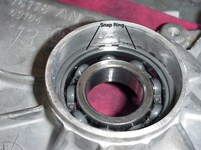
Here is a great picture of the snap ring that must be removed before the bearing can be removed. You need to be careful with both of these parts since they will be used in the new rear case. We tried a pair of snap ring pliers…..a Snap-On pair at that. But, they weren’t the right kind to engage this kind of snap ring and they just couldn’t get a bite on the snap ring.
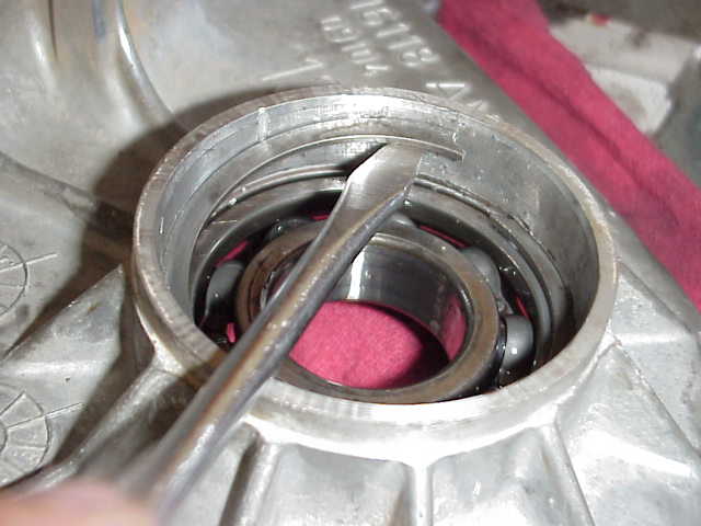
So we resorted to a couple of screwdrivers and surprisingly, it worked really great! Take one of the screwdrivers and pry the snap ring away from the wall. This is pretty easy to do since the ends of the snap ring are cut at an angle that allows you do to this pretty easy. Once you have it away from the wall (which also means it is partially out of the groove), you can slip another screwdriver under the ring and begin to gently nudge it up the side of the housing wall, as seen in the photo above. Continue working the snap ring up the wall in kind of a spiral pattern. You don’t want to leave one end still engaged in the groove while the other end is pushing out of the top, as this might cause the ring to crack in half.
Once the ring was out, we used a ball peen hammer and a drift punch and gently tapped on the “outer” race of the bearing assembly (from the opposite side of the bearing as shown in the above photo). I just walked the punch all the way around the edge of the bearing, tapping as I went. In a minute or two, the bearing was out of the housing, good as new.
At this point, we were half way done! Time to stop and have some lunch, which is just what we did (and you should too!).