NOTE: This conversion alters one of the safety devices (the brakes) on your vehicle. If you should decide to undertake this conversion, it should be performed by personnel who are competent to conduct such alterations to a vehicle. This conversion can result in changes to your vehicle’s handling and braking ability. This is not a step by step set of instructions on how to do it, but rather a summary of the various things I did to accomplish my conversion. Any similar conversion work performed on your vehicle is done at your own risk. If in doubt, consult the services of a professional.
I had been running 35″ tires for a number of years now and I always wondered just where my braking really was in comparison to a stock TJ. It has been years since I drove a stock TJ and trying to recall what it felt like just wasn’t working. A couple of years ago, I installed Grand Cherokee disc brakes on my D44 rear axle and put Performance Friction pads on my front calipers. I also replaced the factory front rotors with good quality Autospecialty Premiums when I installed my Warn hub kit. I had done about all I could to make my TJ stop reliably given the circumstances.
My meeting up with the folks from Vanco Power Brake Supply was kind of a fluke. I got an e-mail from one of the employees (Bree) who asked if I might have some off-road pictures. That led to more e-mail exchanges and I finally ended up talking to Vanco about upgrading my braking system.
The Hydroboost is a hydraulic booster that replaces your factory vacuum booster. The booster is that big round thing that is bolted to the firewall on the driver’s side of the engine compartment. When you press the brake pedal, the booster amplifies the pressure you generate and applies it to the master cylinder. As you know, the master cylinder pushes brake fluid to your front and rear brakes to stop your vehicle. Whereas the factory booster receives its operating power from the engine’s intake vacuum, the Hydroboost relies on hydraulic pressure and flow to make it work. For the TJ, we reroute the output from the power steering pump and use it to power the Hydroboost and still handle the power steering demands of the vehicle. This increased demand means the pump gets upgraded too.
Vanco has done CJs and YJs for a number of years but has had limited experience with the TJs. To be truthful, my first attempt at getting the Hydroboost to work in my TJ yielded less than the expected results. It worked but not as well as I hoped. I had installed a higher capacity power steering pump along with the new booster and master cylinder. By this time, I was working directly with Van himself and he was doing everything he could to help get things working on my TJ. Van immediately sent another system (hydroboost and master cylinder) after we exchanged information about how it was performing. The second unit performed worse than the first and I was baffled as to why things were not working.
I spoke with another Jeeper who had recently installed the Vanco setup on his TJ and he was completely satisfied with the results. I spoke with Van again and updated him on the situation. Blaine Johnson, my friend in CA who had helped with my rear disc conversion and rear shock relocation, had done a couple of booster installs and I talked with him a bit about what I was experiencing. At some point, Blaine and Van hooked up to exchange ideas and comments. After a lot of discussion, it was decided that I was suffering from low power steering fluid flow to the hydroboost (which we later determined was true). What we didn’t know was that there was a manufacturing defect in the second master cylinder I had tried, a brand new Wagner unit.
By this time, Van was pulling out his hair and I was feeling pretty down in the dumps. I had put my stock pump and factory booster back into the TJ so I had a Jeep to drive again. In the mean time, Van made arrangements to drive to Phoenix (he lives in CA) with a trunk full of parts in hand. Toys by Troy had installed a couple of the Hydroboost units too and their results were mixed as well (some really good, some just average). Troy donated some space in the shop and I met up with Van on a Monday to work on my TJ. I took Tuesday off from work just to be safe and to help Van with an XJ install assuming we got my brakes working on Monday.
The time between my second install and Van’ arrival at Phoenix, he had some lengthy discussions with his power steering pump supplier. To make a long story short, the high flow pump that I got for my first install wasn’t flowing enough fluid. When that same pump was hooked up to the second Hydroboost install (with the defective master cylinder), it simply made the situation worse. No wonder install #2 was the pits.
Van arrived in Phoenix on a Sunday and I met him at Troy’s shop bright and early on Monday. The third install worked like a champ! Another pump with verified flow specs was installed in my TJ. We took a new 3/4 ton Hydroboost and new Wagner master cylinder and attach them to the new pump. The results were better than I had seen to date but we were still not quite there. Troy had loaned me his brake pressure gauge kit when I had started this project. After each install, I would check the front caliper line pressure to see how things were shaping up and take the vehicle for a couple of test drives. Van decided we should try a beefier Hydroboost. Out came the 3/4 ton booster and in went the 1 ton unit. A quick bleed of the power steering system and we were ready to look at the pressure gauge numbers.
“Houston, we have brakes!” Oh yeah, finally I was seeing the results that Van kept telling me I would see. It was great. TJ Hydroboost brakes feel so much different than vacuum booster brakes. The first thing you notice is the firm pedal. It moves ever so little to apply the brakes. I let several friends that happened by Troy’s shop take a test drive. They were totally impressed with the way it stopped. The best comment was “Oh, that is what brakes are suppose to feel like!” The 1 1/8″ diameter bore on the master cylinder is larger than the factory master cylinder. If one simply attached a bigger bore master cylinder to the stock vacuum booster, you would actually see a decrease in brake performance. However, when the larger bore master cylinder is coupled with a higher pressure booster, you will see more pressure at the calipers (along with less pedal travel and effort).
Anyway, before I get into the install procedure, I just wanted to relate my experiences in getting this project completed. A very big thanks to Van for the unending support and effort he expended to help get my install problems resolved. I learned a lot during this process and I know that Van will apply this experience to his 20+ years of doing brake systems to produce an excellent and reliable TJ Hydroboost kit for everyone else to enjoy.
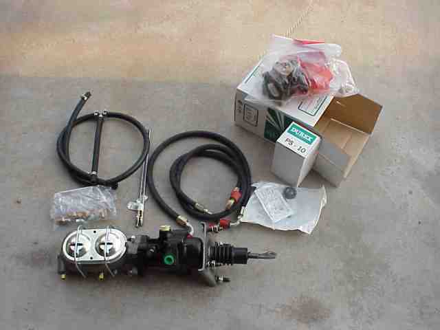
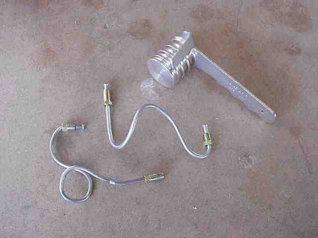
OK….to the install details. When the box from Vanco arrived, I pulled everything out to have a good look see. The master cylinder was already bolted to the hydraulic booster. Two AN-6 terminated high pressure hoses (one goes from the power steering pump to the booster and the other goes from the booster to the steering gear box) are included with appropriate adapters. The remainder of the kit consists of several feet of pre-cut low pressure return hose with a “T” fitting and hose clamps and a pair of pre-flared 3/16″ steel brake lines with appropriate fittings.
The hydraulic booster puts an additional demand on your power steering pump. Since I was still running the stock pump, I upgraded my pump to a 1500 PSI unit that flows about 3.4 GPM of fluid. Vanco also included an in-line power steering fluid filter to be used with the new pump. The install instructions from Vanco was written for pre-TJ vehicles but I knew that before the box of parts arrived. With only a few hoses to attach, it wasn’t difficult at all to figure out what went where.
The first step of this project was to get real world data that could be used in the “before” part of our project. Remember, this project is suppose to help me get back to stock braking performance (or better) and I wasn’t going to be happy with a “it sure feels better” kind of comment when all was said and done.
MikeW came over on a Saturday morning and we headed over to the west side of the valley where some freeway construction provided us with a dead end asphalt 2 lane highway. Such a road would be perfect for doing some 60 MPH deceleration tests. So, with video camera in hand, we jumped in the TJ and headed off to do some “panic stops”. The last three stops were the best (it took me a couple of times to get the feel of mashing the brake pedal for all it was worth) and yielded distances of 147, 138, and 136 feet. In contrast, the first stop was right at 180 feet. There was approximately 5 minutes of time between each braking period so I don’t think we saw much in the way of brake fade, etc. due to heat build up on the rotors.
Next, I wanted to see just just how much brake line pressure I was getting before I changed anything on the TJ. I wanted to see just how much force was being applied to my front calipers. With the engine at idle (max vacuum for the stock booster), MikeW pushed the pedal to the floor a few times and we were able to record 2000~2100 PSI as max pressure at the front calipers. With the last of the pre-project number gathering out of the way, it was time to get on the actual installation.
Note: Since my install, I’ve been able to test a couple other TJs to see what kind of pressure their stock systems were generating. An ’04 automatic equipped model came in at 1500 PSI and an ’00 automatic was putting out 2000 PSI. In contrast, the ’91 XJ that Van and I did an install on measured just 1100 PSI with the stock booster. The single diaphragm vacuum boosters of that era do put out less pressure than the dual diaphragms used in the TJs.
MikeW and I decided we needed a break from my 8″ lift so we drug out the floor jack and got busy. We removed both front tires and lower the axle down onto the shortest jack stands I had in the garage. While not perfect, it was much easier to reach in to the engine compartment. In fact, the milk crate I stood on last week, while replacing my water pump, was just about the right height now. With that out of the way, we made some work space in the engine compartment by removing the radiator overflow container and the windshield washer reservoir. With them removed, access to the power steering pump was much easier.
For complete details on how we performed the power steering pump replacement, see this write-up. If you already have a 1500 PSI, 3.5 GPM rated pump, you won’t have to worry about upgrading your pump to meet the increased demands from the Hydroboost.
NOTE: Since this write-up was done, now a year ago, I recently installed a new pump with a remote reservoir. If you are replacing your stock pump with this configuration, check out this write-up for details on how I did mine. Obviously, the information provided in this write-up in regards to hooking up the return lines to the stock reservoir will be different. The write-up for this new pump installation includes that information.
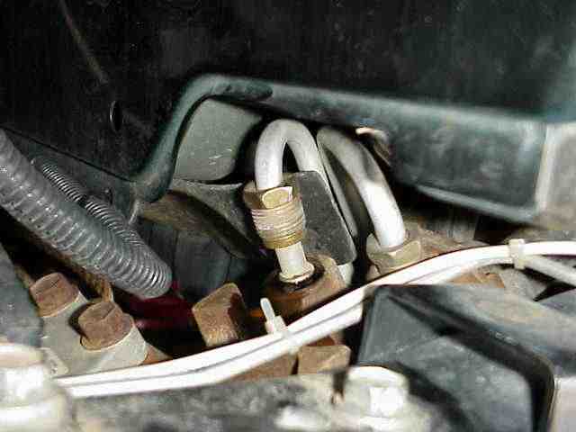
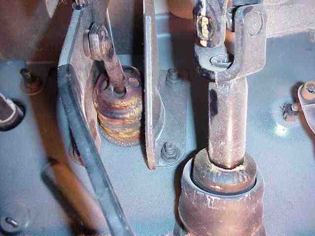
In addition to the steps outlined in the PS pump write-up, the pic above (taken below the driver’s side headlight, on the inside of the frame rail) shows the high pressure line on the steering gear box that is removed and replaced with a hose from the kit. The factory hose that originally connected the pump to the gear box is not used. Take the hose and stuff it into a plastic bag (the one that the new pump came in would work just fine) and keep the hose on your parts shelf. Some Saturday afternoon, when the dealership parts counter is closed, your buddy will call you and ask if you still have that old hose (because his started leaking and he has a night run coming up in just 2 hours!).
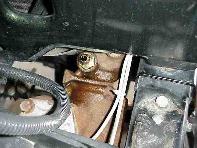
One of the supplied AN-6 fitting adapters is inserted into the steering gear box. This adapts the new hose to the steering box. Of the two supplied hoses, you will be using the longer of the two hoses for this connection. The other end will be connected to the hydraulic booster’s output port. While you are down here, you will notice that the low pressure return line (the other fluid connection on the steering gear box) goes up to the reservoir on the power steering pump. Remove the hose clamp and then the low pressure hose from the steel section of the steering box’s line. You will later replace this return line with that provided in the kit.
After the power steering pump was installed, we turned our attention to the removal of the factory booster and master cylinder. The picture above shows the connection of the booster rod to the brake pedal (taken from under the dash). I had removed the small metal clip that kept the booster rod secured to the brake pedal when I snapped this picture. The booster rod can be moved slightly to the right and slipped off of its mounting point on the brake pedal. There are four bolts that surround the pedal rod where it comes through the firewall. Once you have removed the lines from the factory master cylinder and disconnected the prop valve mounting bracket, these nuts will be removed and the vacuum booster can be removed from the firewall.
Vanco Hydroboost Brake Conversion
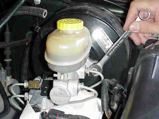
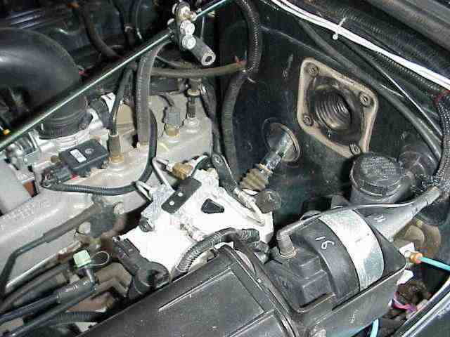
Back on the other side of the firewall, we have a couple of things to do before the factory booster and master cylinder can be removed. Remove the lines that connect the master cylinder to the combination valve. Grab some paper towels as you will have brake fluid dripping here and there. The mounting bracket for the proportioning valve is mounted to the studs that hold the master cylinder and booster together. Carefully remove the two nuts and then slip the mounting bracket off the studs. As I wanted the booster and master cylinder to remain as one piece once I removed it from the TJ, I put the nuts back on and snugged them down.
Also note there is a rather large vacuum hose (the vacuum source that was attached to the booster) that I have disconnected in the above pic. You need to seal off the hose so that you do not suck air into your intake manifold and lean out the engine (which can overheat it) or get one of those rubber caps that fit over the fitting on the intake manifold to seal it. I folded the hose in half (causing the hose to collapse on itself) and then used a couple of big zip ties to keep it squeezed together. A bolt, hosed clamped into the hose, would work equally well and is what I’ll do once I find the right bolt in highly unorganized bolt collection. If you are looking at the above combination valve and you notice it does not look like yours, not to worry. It is from a ZJ and was installed after I added disc brakes to the rear axle.
With all the above items disconnected, have a friend remove those 4 nuts from the other side of the firewall while you hold the booster and master cylinder. Once the nuts are removed, carefully extract the entire unit from the hole in the firewall. There will be a rubber gasket stuck on the firewall (more than likely) that covered the pedal rod going through the firewall. Remove it as it is no longer needed.
You will notice that the mounting studs that hold the hydraulic booster to the master cylinder are about a 3/16″” further apart than the holes on your proportioning valve’s mounting bracket. (that is true for the ZJ mounting bracket which I believe has the same dimensions as the TJ) I grabbed a cordless drill and enlarged the holes to 3/8″. This took care of some of the problem but they still didn’t quite fit. With a Dremel tool, I cut a small piece out of the end of the mounting bracket so I could spread the far end of the bracket open, much like a those U shaped electrical terminals. It took just a couple of minutes to open up the bracket enough so that it would fit over the mounting studs. Once the nuts were tightened back down, you could not tell any handiwork was done.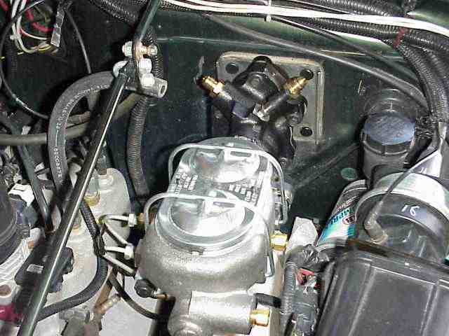
It was time to mount the booster (and master cylinder) to the firewall. This time, it is your turn to lay on your side to get up and under the dash. Have your friend carefully put the booster rod through the large opening and line up the mounting studs (two of them are pressed into place and two are loose, although it is possible that Van may be using regular bolts in future kits) with the corresponding holes in the firewall. You will also notice about now that the overall length of the booster and master cylinder is an inch or two longer than what you just took out. (yes, I measured mine before I started the install and realized that I could make it fit with just a little alteration) I think it is called the purge solenoid and is mounted to the side of the rather large canister that bolts to the fender well, right next to the master cylinder. The purge solenoid and its myriad of small noses was slipped off of its mounting tab and the tab cut off with the Dremel tool. That provided adequate clearance for the master cylinder to fit where it needed to be. I used two zip ties to reattach the purge solenoid to the canister bracket. A small bracket made from light gauge metal could be fabricated and the purge valve remounted if so desired.
Vanco Hydroboost Brake Conversion
As mentioned back on the first page, you have a pair of twelve inch long 3/16″ diameter lines, complete with fittings, that will need to be properly bent to fit between the master cylinder output ports and the proportioning valve. OK, so I’ll confess that my bending is not something I am proud of, but like MikeW said, they work and who is going to be looking at them when the hood is closed? The master cylinder is divided into two sections (as are most) and the larger section (at the front of the master cylinder) needs to be connected to the combination valve port that feeds the front disc brakes. Want to play it safe, follow the lines coming out of the combination valve just to make sure you have the correct line identified. A single line goes to the rear axle while the two front calipers are connected via separate brake lines. I picked up an $8 tubing bender at the NAPA store which was worth the money. It would have been more beneficial if the bend radius had been smaller (which it easily could have been). Take your time and work on getting the steel lines to line up properly with the ports. We unbolted the canister that was on the fender because it was in the way while trying to test fit the lines. I tried to find a pair of 90 degree fittings which would have made the connections at the master cylinder much easier to do….but, no luck. Take your time and you will get it, even if it looks as bad as mine. At this time, do not connect the brake lines. We will get to that a little bit later. 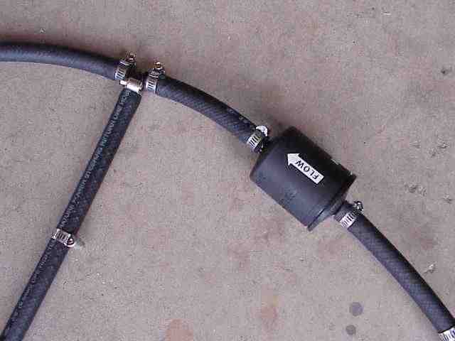
Next, connect the 3/8″ low pressure return line to the steering box, pump reservoir, and Hydroboost. The filter came with no hose clamps so I made a quick dash to the parts store to pick some up….all of my spare clamps were too big. The middle hose of the “T” connects to the power steering pump reservoir. The short leg connects to the low pressure return port on the steering gear box and the long leg connects to the low pressure return port on the hydraulic booster. Take a few minutes to properly determine the best position for the filter. You will find you are near the steering column shaft and you would not want things rubbing against each other as the steering wheel is turned. I cut the hose and inserted the filter (as seen above) and then trimmed a little more off the free end to get the hose to route where I wanted it. Just remember, measure twice, cut once….and you will be good to go.
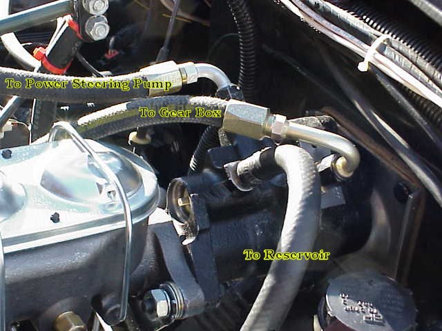
The hoses on the hydraulic booster are next on the list. Of the remaining adapters, screw two of them into the “to power steering pump” port (the inlet connection) and also into the “to gear box” (the outlet connection) port. Then attach the hoses to the adapters. The fitting on the “to reservoir” port gets the last hose which is the long leg of the low pressure “T” return line. It is held in place with the supplied hose clamp.
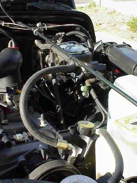
I zip tied (better than duct tape!) the high pressure line (between the PS pump and the hydraulic booster) in place so as to keep it out of the way. In general, always pay attention to the way in which you route hoses and lines carrying fluids. You do not want them touching any rotating objects (fan blades, serpentine belt, pulleys, etc.) nor do you want them to abrade on any sharp corners.
One thing that I noticed was that the pedal rod (the part that connects to the brake pedal) is probably a little different in length than what you removed. No problem except that it will probably cause your brake lights to remain on even though you don’t have the pedal depressed. Not a problem….the TJ has an adjustable brake light stop switch. If you look under the dash, the stop light switch is mounted on a bracket that sits in close proximity to the brake pedal. There is a spring loaded plunger on the switch that is actuated by the brake pedal when the brake pedal is at rest (no pressure on it). To adjust the switch plunger, first locate small pair of needle nose pliers. Push the pedal down slightly and carefully pull on the switch plunger with the pliers. It will take a little bit of force but it will slide forward. Let go of the pedal and as it returns to normal, it will push the switch plunger back into position and you will hear a little ratchet sound as it does. Congrats, you have just adjusted your brake light switch for your new pedal rod.
Vanco Hydroboost Brake Conversion
That just about wraps up the Hydroboost installation. At this point, you should bleed the air from your power steering hoses. The procedure for bleeding the lines is here at the bottom of the page. Take your time and do a good job on it. Your pump will appreciate your efforts!
Next comes bleeding the brake lines. Although I had never done it before, I took Van’s advice and bench bled the master cylinder before hooking it to the TJ’s combination valve. It is not mandatory that you do it, but from what I witnessed, it sure does get the air out of the system a LOT easier.
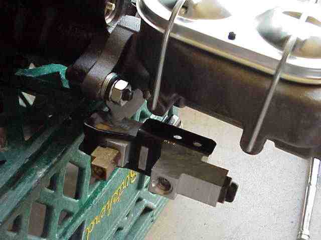
To bench bleed, get some rubber hose that just fits over the end of the steel lines you bent (not the fittings, just the flared end of the line itself). Screw one end of the line into the master cylinder and slip the hose over the other end of the line. Note that you won’t have these lines “routed” in the manner that you bent them for….just get them attached to the master cylinder in such a fashion that you can get to the other end. Now put the free end of the hose into the master cylinder as shown in the above picture. Do the same for the other port on the master cylinder. Fill both sections of the master cylinder with fresh brake fluid so that the ends of the hoses are completely covered (and then some).
Now, SLOWLY push the brake pedal (you can do it by hand if you wish) down as far as it will go and then release it. Wait about 5 seconds and repeat this process. After several minutes of doing this, you should notice that the bubbles that were coming out of the hose and up from the little ports inside the master cylinder have all but stopped. Congrats….your master cylinder is now bench bled and all the air that was in it is now gone.
Remove the two rubber hoses. Now reposition the lines so that you can connect the combination valve to the master cylinder. If it has been a while since you have flushed out the brake fluid in your vehicle (and it probably has), you can do a regular brake bleed at all for wheels. Once you get fresh clean fluid coming out at each wheel, you should be quite confident that you have gotten out any air that may have gotten into the system during your install and you’ll have fresh fluid to boot!
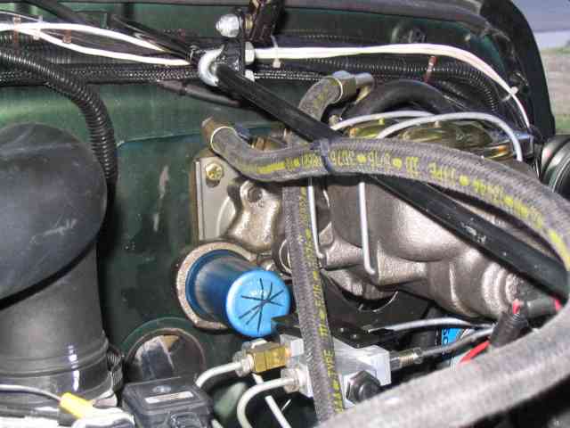
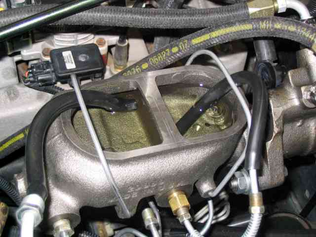
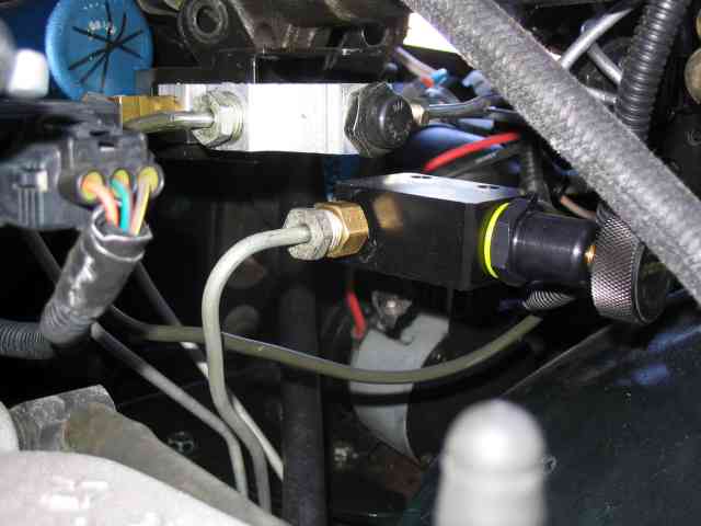
The previous pics of the Hydroboost were taken during my first installation. The unit used at that time was a 3/4 ton model as I mentioned earlier. The picture above was taken after I got my system working correctly with the 1 ton Hydroboost. The hose connections are identical on both units. The major difference that you can see is the blue accumulator in the above picture. This accumulator stores a gas charge and fluid so that the brakes can be applied a couple of times even when the engine is not running (much like the vacuum booster will keep a couple of pumps available until the vacuum canister is emptied).
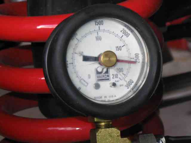
Here are the final results of my install….2600 PSI on the pressure gauge. Not too bad and that is right about where Van expected it to be. Actually, I get anywhere from 2200 to 2600 depending on my engine speed. With the engine just a little above idle, about 1500 RPM or so, I’ll hit max pressure. Not too bad at all! These numbers are right in line with the other Jeeps that Van and I worked on. We were getting 2200 to 2400 PSI on a TJ and XJ respectively after installing 1 ton Hydroboosts on them.
As for real world testing, MikeW and myself went out to the same dead end highway and I did a couple of 60~0 MPH deceleration runs. As expected, my brakes are working much better now….or perhaps I should say that I finally have enough pressure to really lock up the brakes. Of course, locking the brakes is not the fastest nor safest way to come to a rapid stop. With the extra caliper pressure, my rear brakes are grabbing a bit more than desired and the resulting lock up causes the rear end to start to come around (normal when locking up the rear brakes). So, as I kind of suspected, I’ll be picking up an adjustable proportioning valve to install in the rear line. This will allow me to set up the front to rear bias and prevent the rear lockup that I was experiencing. Just for grins, MikeW gave his TJ a try too. While he has the stock booster and proportioning valve on his, he also has a Ford 9″ rear axle with drum brakes….and those drums are much larger than the TJ drums. He too has too much rear brake pressure as he locked up the rears all too easily during his panic stop.
I think that about wraps up this installation. When I get my adjustable proportioning valve for the rear, I’ll add those details onto this write-up to make it a “complete” project.
Again, many thanks to Van for all of his help. It is always great to work with a vendor that provides this level of customer service. When you decide to put a Hydroboost on your TJ, tell Van you read about it here. You are looking at about $825 for a complete kit (pump, Hydroboost, master cylinder, hoses and adapters). If you already have a high flow pump, then subtract $125 from the price. Van said he would do group purchases starting at a minimum of 5 people which would drop the price by $100. By the time you read this, pricing may have changed so don’t hold me to the above numbers. They were current when the write-up was done but most likely are not now.
Vanco Hydroboost Brake Conversion
OK….like they say…”and now the rest of the story”.
I spent some time on-line exchanging e-mail and forum comments with a couple of friends. I was looking for personal experiences from those that had put in a valve to reduce the rear brake pressure and thus, the rear brake lockup. Within 24 hours, I had the first hand information I was looking for.
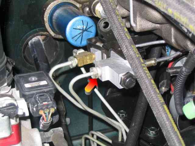
The colored arrow in the above picture is pointing to the brake line connection on the combination valve that goes to the rear axle on the TJ. This is the line that will be removed from the combination valve. A Wilwood adjustable proportioning valve, model # 260-2220, was purchased on-line (I obtained mine from www.jegs.com) for about $50 delivered to my door. I found other adjustable prop valves for less but decided to pay the extra $10 and get one with the Wilwood name on it. The adjustable valve allows pressure to be reduced to a maximum of 57% of the inlet pressure by simply turning the adjustment knob. The valve is put in-line (after the combination valve) with the brake line feeding the rear axle and adjusted so that the rear brakes lockup just after the front brakes begin to lock.
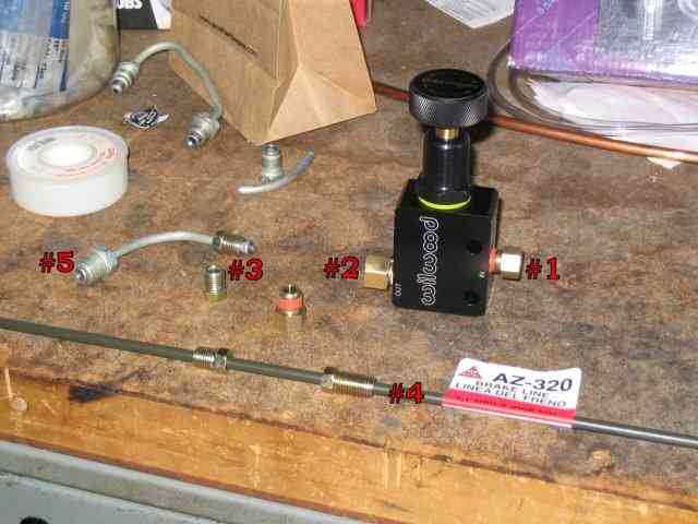
Here is what the Wilwood adjustable proportioning valve looks like. How you decide to hook up the adjustable proportioning valve is entirely up to you. Here is how I decided to do it (not saying it is the best method, but it worked for me.)
The Wilwood valve comes with two adapters that you screw into the inlet and outlet ports. I have installed one of these and it is shown in the above picture as item #1. It is designed to take a standard 3/16″ brake line flared connection, which is what item #4 is….a 20″ long pre-flared line. Item #5 is a flared fitting that was salvaged from the line that originally connected the stock master cylinder to the combination valve. It is a metric fitting (a 14mm brake line wrench fits it) and just happens to be the same size as the one which appears in the picture at the top of this page (the one with the colored arrow in it). Item #2 is an adapter that I picked up at the local NAPA store. It is sized to fit fitting #5. I had picked up a couple of regular 3/16″ fittings (items #3) before I found item #4 that came with the same fittings (hey, it never hurts to have a few extra brake fittings, right?)
By now, you should be able to figure out what is going to happen. Brake line #4 was cut (not all 20″ of it is needed). One of the fittings on it was used and the other one was removed. In its place, fitting #5 was slipped onto the line. The end of the line was then double flared. This finished line was used to connect the combination valve’s rear brake port (colored arrow in photo at the top of the page) to the inlet port (item #1 on the Wilwood valve). The rear brake line (previously removed from the combination valve) was then attached to the outlet port of the adjustable valve (item #2 on the Wilwood valve).
Here is the Wilwood proportioning valve as installed in the TJ. I located it below and slightly forward of the combination valve. The most forward port on the combination valve, which is the single line that goes to the rear axle, is now connected to the outlet port on the Wilwood valve. The section of brake line that I cut and flared myself now connects the combination valve’s rear line port to the inlet port of the Wilwood valve.
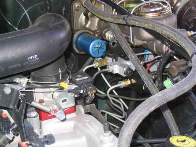
Here is another picture with the camera backed off just a bit so you can get a better idea of where everything is positioned. My plan is to make some kind of lightweight mounting bracket for the combination valve and the Wilwood valve so they can be connected together. Right now, everything is held in position by the rigid brake lines. I believe it would be better if things were supported by a bracket rather than the lines themselves.
MikeW was not able to make it over to help with the final testing due to some out of town company that came to visit. So, I got in contact with a couple of other Jeepers, Dan and Mark, and they agreed to come over Saturday AM and help out.
By the time Mark arrived, I had installed the Wilwood valve and was waiting for a spare pair of feet to actuate the brake pedal while I bled the air from the new lines. About the time we were finishing that up, Dan pulled up. After the typical 15 minutes of talking Jeeps and brakes and stuff, we headed out to do some deceleration testing.
I was a little apprehensive after the previous weeks testing. I set the Wilwood valve at the mid point and tried a couple of 35 MPH stops. The rears were still locking up so I dialed in a little more restriction on the Wilwood and gave it another try. Better….but still a little lockup on the rears. I gave it another 1 1/2 turns ( it is a 10 turn adjustable valve) to reduce rear pressure even more and then tried another stop, this time from about 45 MPH. Oh yes…..this time, we had the front tires howling (and I do mean howling). I split the difference from the previous adjustment and open the valve up a bit in hopes of getting the fronts and rears to lock up virtually together. Not too bad….several more 45 MPH stops indicated I was pretty darn close to a good front to rear bias.
By now, the tires and warmed up some and the smell of rubber was in the air. I wonder how many miles I burned off of the tires this morning? Oh well, all for a good cause. We broke out the tape measure and ran a series of 60~0 MPH stops. We got distances of 137′, 140′, 133′, 107′, and 144′. On the 4th stopping test, (the 107′ distance), I tried something different. Instead of just hitting the brakes as I had been doing, I immediately let up on them (just a bit) when they started to howl and then reapplied the brakes very hard….kind of like doing a two step approach to stopping. In that stop, there was almost no tire howl on the second application of the pedal until just the very last few feet as I came to a stop. I was impressed with the results (and my tires were probably saying thank you too).
Van had told me I would have to learn how to stop all over again and although I didn’t believe him at first, I was beginning to think that there was something to what he had said. The longer stop (last one) was an attempt at hitting the pedal three 3 times…(hey, if two times improved things, three times would be better, right?)…but I found that there was too much time wasted in the motions of releasing and reapplying the brake pedal…which resulted in a longer over all distance. So yes, I can stop in a shorter distance but it will require me to practice this procedure a few more times in order to gain the most benefit from it. Here is the video that was taken while we were testing the new setup. As you can see, the howling brakes was not the shortest stopping distance….having them just at the edge of locking up yielded the shortest distance (but I miss the cloud of blue tire smoke!) On the flip side of the coin, for those folks that have installed a 4:1 Tera or an AtlasII transfer case, you will see greatly improved results in your ability to stop the vehicle when in 1st gear and low range.
I think this about wraps up the install and testing. Am I happy with the results….yes I am. I now have ample brake pressure to stop the TJ. Do I need to work a little more on my technique, yes I do….no different than adapting to any other modification that is made to the vehicle. The change in brake pedal behavior is an added benefit, in my opinion. If you are tried of trying to put your foot through the firewall in an attempt to stop your vehicle, I would urge you to consider a Hydroboost.
Take care and remember to TREAD Lightly!