Everyone knows that off-roading at night is commonly done, especially when the weather is great which makes for an awesome night out. Sometimes, we find ourselves coming off the trail well after dark because of a breakdown (or worse, an accident). It wasn’t our intention to be “out after dark” but somewhere along the way, that rear axle shaft missed the memo and so there was a delay while it was replaced. (you do carry spare parts, right?) Regardless of the reason we find ourselves on the trails in the dark, common sense dictates that we have good lights to ensure that we can navigate the trail and get home safely.
Beefing up the lighting system on a Jeep (or any off-road vehicle for that matter) is one of the most common upgrade projects there is. There are lights to fit most any budget and aside from a few hand tools, they are easy to install. If you’ve not installed lights before, this particular light bar from Extreme LED Light Bars would be a good first time project. It is as close to plug and play as you can get, in my opinion. If you are a LED veteran, Extreme LED has some high end units that will certainly turn your night into day.
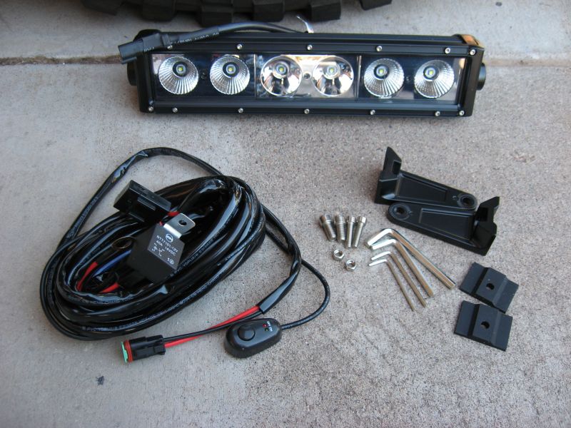
Here is the lighting kit I decided on…..a LED light bar, the R-1 14″ model, rated at 5,400 lumens. I got the switch kit for it as well. Aside from something to drill a pair of mounting holes with, you don’t need any other tools. Hex wrenches are included for the supplied mounting hardware and the LED enclosure.
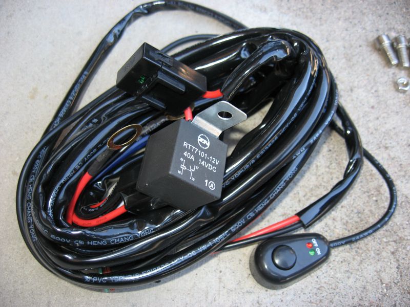
The switch kit was one of the better solutions I’ve ran across since doing 12V electrical projects on my vehicles. A socketed 40 amp power relay does the heavy lifting, so to speak. Having the relay plug into a socket means it is super easy to troubleshoot and even better, you can borrow the relay and use it in another circuit (yes, it is the most common 12V relay pin configuration made) if forced to do so. An inline fuse holder (with fuse) is already wired and protects the wiring and more so, your vehicle, from melting down should a short occur in the circuit. The push style ON/OFF power switch is integrated, by an electrical plug, into the harness. This makes it easy to install in your cab with the wire pigtail going through a grommet in the firewall to plug into the rest of the harness. The switch itself simply controls the power relay. Push the switch to ON, the relay energizes and you apply 12 volts to the light bar. Push it again, OFF, the relay drops out and the light bar is dark. OK….enough basic electricity teaching….back to the project!
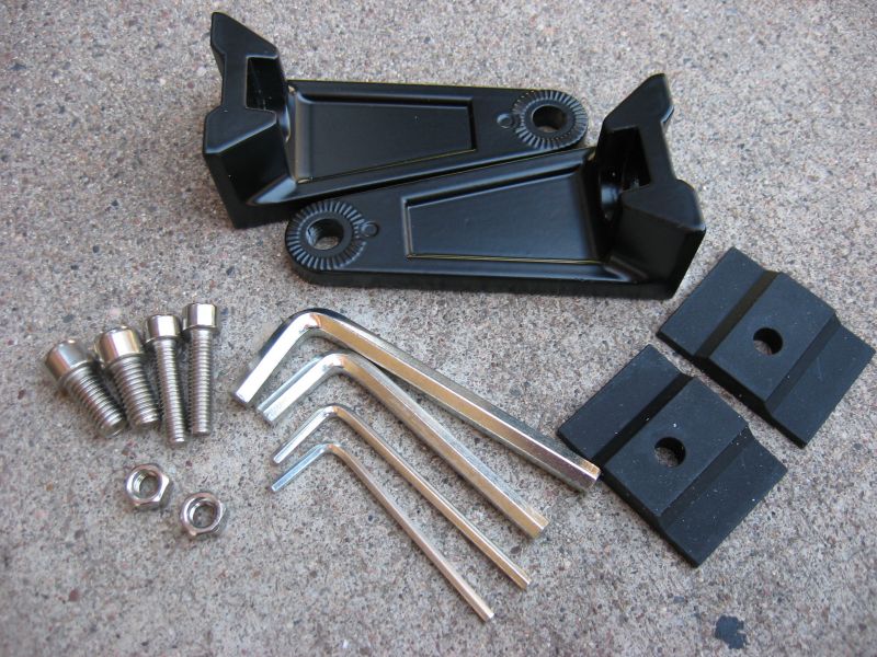
The light bar’s mounting kit is complete and even includes rubber isolators for the mounting feet. (nice touch!) The mounting feet can be mounted inwards or outwards (more on that later) to better fit the footprint the light bar will be mounted on. I opted to swap out the mounting bolts for the feet as I wanted to use Nyloc nuts and didn’t have any that fit the supplied hex bolts. I dug around in my nuts & bolts drawers (every Jeeper has those, right?) and found a couple of 1/4″ bolts that would be suitable for the job.
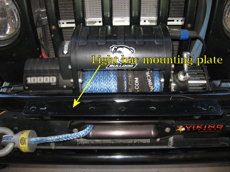
My TBT front bumper came with a detachable light mounting plate/bracket. It mounts in the same holes that can be used to secure a Hi-Lift jack. I dug through the shelves in my garage and located the plate. A couple of bolts later, I had it secured to the front bumper. At one point in time, I had the plate mounted on the bumper with a pair of incandescent off-road lights but one of them failed and the pair were removed, along with the plate, and the lights tossed in the trash. Such is the fate of the typical $39.99 off-road light kit.
Of course, Mr. Murphy, of the infamous Murphy’s Law, was working uninvited on my project too. The best possible pair of mounting holes in my mounting plate were off by about 3/8″, with the mounting feet on the light bar oriented outwards. I decided my best option was to attach the feet to the light bar so they were pointing inwards (towards each other). This would allow me to drill a new pair of mounting holes that were well clear of any existing holes in the plate. A few measurements using a steel rule and then a couple of hits with a center punch located my new holes. Note, this is the place were you measure twice and drill ONCE! After I finished drilling a new pair of holes, it was time to mount the light bar and proceed with the wiring.
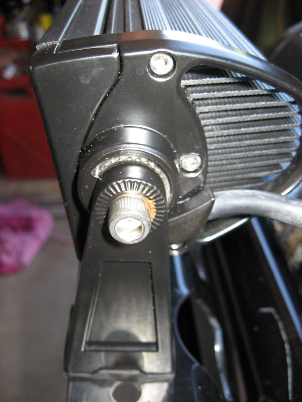
As I mentioned earlier, the “L” shaped mounting feet can be flipped so they point towards or away from each other. One thing I noticed and do appreciate are the matching notches on the feet and light bar body…..once tightened via the mounting screw, they engage each other and do not allow the light bar to rotate which is a problem I’ve seen several times on other off-road lights. These notches are on both sides of the mounting feet (good design) which allows you to position the feet either way and still have a solid mount.
Since I was using steel bolts on an aluminum housing, I dug out my anti-seize compound and coated the screw threads before screwing the feet to the housing. You can see a little bit of anti-seize around the screw head in the above photo. It is no doubt over kill but then again, I know I won’t have an issue should I decide to pull this apart in a couple of years. Folks in less forgiving environments (Arizona is quite forgiving when it comes to such things) no doubt use anti-seize compound by the case (or they should).
More LED Light Bar
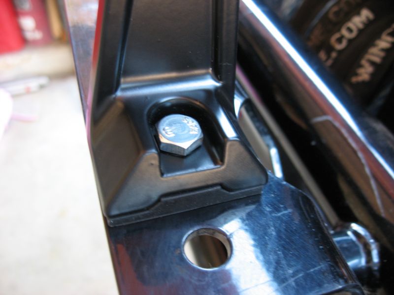
You can see the rubber isolator sandwiched between the mounting foot and the mounting plate. I like this idea a lot. Once I was ready to tighten the mounting bolts, I did so until I started to see a bit of bulge from the rubber isolator. With the Nyloc nut on the mounting bolt, I new it would not vibrate loose and the rubber would give me the benefit of some “shock mounting”. I’m not sure if that was the intended purpose but for me, it looks like it will do just that and so it is.
With the remaining mount bolts tightened, here is a pic of the LED light bar on the mounting plate. I would have preferred to mount it to the bottom of the bumper’s mounting plate but it would have placed the light bar too close to the winch fairlead. The last thing I need is the synthetic winch line getting in a fight with the light bar. The light bar looks very well made but it would not stand up to the forces of an off-angle pull during a vehicle recovery.
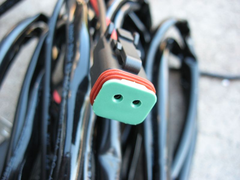
Here is a pic of the switch kit’s plug that attaches to the wiring pigtail on the light bar. I’m not sure if this is a water proof or water resistant connector. Regardless, it will go a long way in helping to keep the pin contacts corrosion free. Corrosion on electrical connections is probably the most common cause of component and/or circuit related failure.
Speaking of water proof, I was doing some digging on the Extreme LED Light Bars web site and found specs for the LED light bar itself. It carries an IP67 rating which according to the FAQ on the web, breaks down to this:
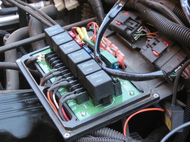
I routed the switch kit harness from the front bumper into the engine compartment following the same route my winch control cable travels. Once the harness was inside the hood, I cable tied it to the existing harness and routed it to The Source power center. By the way, if you aren’t familiar with the sPOD and The Source power center, click on that link. It is an outstanding product for the serious off-road enthusiast.
I cut the switch kit’s main power cable about 6 inches short of where it terminates in the power relay socket, after checking to ensure it would be long enough to reach the power center. Why? I had two empty slots (one now) in the power center. With an integral fuse and power relay, I did not need the rest of the switch kit. But it isn’t wasted…..I left more than enough wire length coming off the switch kit’s power relay to allow it to be used in some other project (probably by a friend). Here is a good place to mention that the light bar is reverse polarity protected so if you are clumsy enough to attaching the power leads backwards, your investment won’t go up in smoke. Personally, I’ve never relied on anyone’s reverse polarity protection and always double check my wiring before flipping the switch. That’s just me….what can I say.
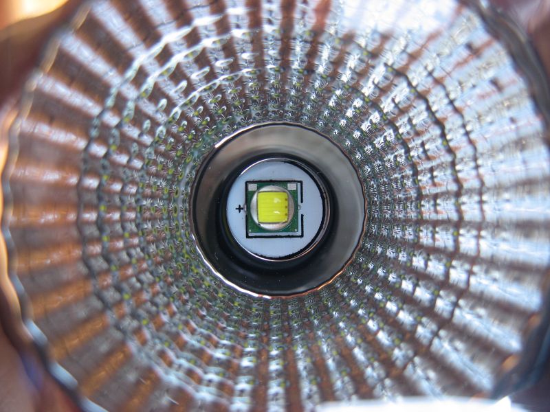
Using the macro setting on my camera, I snapped a close-up of one of the LEDs in the light bar. Amazing it is to think so much light is produced by such a tiny little “thing”. This is what converts the 12V DC electrical current into useful light…and lots of it too. This newer generation of LED design is very efficient in producing light.
Looking at the specs on the web site, I noticed that this 14″ light bar, with its 6 LEDs, draws a mere 4.26 amps of current at 12 VDC. That’s just a bit over 50 watts of power converted into 5,400 lumens of trail illumination. What I like is that you don’t have wiring carrying a high current load in the vehicle. That means little to no chance of the wiring over heating when it bundled with other wires (don’t know about your TJ, but bundling wires together is very common in my TJ).
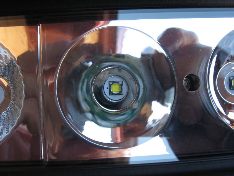
I wanted to comment on one other thing…..the reflectors used in the LED light bar. This reflector is very smooth while the previous close-up was not. Why so? This light bar provides both spot and flood lighting. The two middle LEDs use spot light reflectors (smooth) and produce a 8-10 degree beam of light. This reaches far down the trail or further out into the field to help illuminate objects at distance. The two outer pairs of LEDs have flood reflectors, producing a light beam that covers a 90 degree area in front of the vehicle. This gives the driver improved coverage of what is close up (think rocks in the trail), ditches, tree branches, turn offs, etc. So this specific model provides both long and near distance illumination which is a good combination for sure.
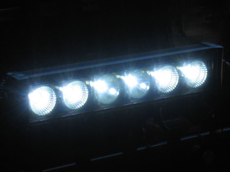
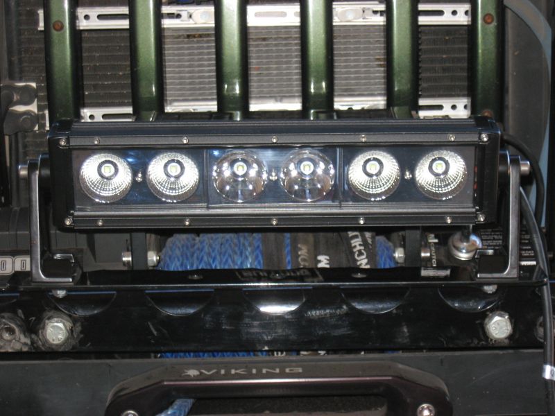
The wiring was almost completed. I used heat shrink tubing and my heat gun to provide an extra measure of protection for the crimped on terminal connectors I installed on the power leads. With the new leads attached to the power center, I put the cover back on and flipped sPOD’s switch for circuit #2 and the LED light bar jumped to life…..well, OK, it didn’t really “jump” per say…..I had the mounting hardware snugged down pretty well. But it did noticeably light up the interior of my garage even though it was a bright sunny day. The above pic was taken of the LED light bar with the TJ parked in my driveway. Obviously my camera really cranked down the automatic f-stop to get proper exposure for the pic.
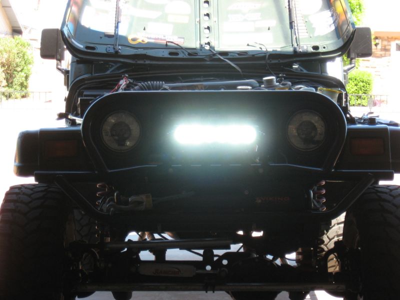
Another pic snapped from the back of my garage. I like the centered location of the light bar’s position. The mounting plate for my TBT bumper provided a perfect mounting platform for the light bar. While I would have liked to have gone with a physically larger light bar, I didn’t really want to deal with the extra work of fabricating a platform/plate that would handle the larger footprint.
After I read my camera manual (where did I put it?) and figure out how to take night time photos without a flash, I’ll see about getting a couple more posted here (assuming they turn out).
Well, that is about it for now. You’ve seen how easily this LED light bar kit was put on the TJ…..and I know you can admit that even you can do it even if you’ve no prior wiring experience. It is a very straight forward lighting project and as I said, a good one to get you started. Check out the various LED lighting solutions available at Extreme LED Light Bars as they have a good variety of light bar and pod solutions with a good selection of styles and price range.
Remember, be safe and remember to TreadLightly!