NOTE: This conversion alters one of the safety devices (the brakes) on your vehicle. If you should decided to undertake this conversion, it should be performed by personnel who are competent to conduct such alterations to a vehicle. This conversion can result in changes to your vehicle’s handling and braking ability. This is not a step by step set of instructions on how to do it, but rather a summary of the various things I did to accomplish my conversion. Any similar conversion work performed on your vehicle is done at your own risk.
Somewhere along the way, I got wind of a little mod that ended up on my California buddy’s TJ, which would just happen to be Robert Yates. Robert’s TJ was something of a test platform for this rear disc brake conversion. A mutual friend had done some axle work on one of his TJs which sparked the idea for a rear disc conversion on a TJ’s Dana 44 rear axle. Robert’s TJ was the first candidate to get the conversion….I guess you could say it was the prototype. The results made Robert a happy camper.
I saw some pics posted on a web site and read some of the comments written by Robert. I was impressed to say the least and decided to give it a try, if at all possible. So….I found myself scrounging for parts. I posted an e-mail on the local club e-mail reflector and found some parts from another Arizona Jeeper. I needed the rear disc brake assembly from a ’95 to ’98 Grand Cherokee’s Dana 35 axle. After receiving the D-35 brake parts from a ’94 Grand Cherokee (hey, it was close), I visited the local Jeep dealership to acquire a few new pieces for the disc brake assemblies. Some of the e-brake parts were missing and I needed to replace them before we could start on the project. I can tell you that getting these parts from the Jeep dealership is rather pricey (I know, tell you something you don’t already know). OK….what I found out later was that I could get a complete hardware kit, which included all of those little parts that are used in the e-brake assembly (clips, pins, star adjuster, springs, etc….all of them) from a good brake parts warehouse. Just ask for a hardware kit and you’ll have all those nice new parts to replace the old rusted ones you get from the donor vehicle. (been there, done that….spent too much money at the dealer!)
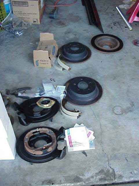
Basically, this is what I used:
complete ZJ rear disc assemblies including e-brake cables
two bearing retainers
new seals for axle shafts
new custom axle backing plates
eight 3/8 x 1 1/4″ SAE fine thread bolts in grade 8 and upset lock nuts
Currie brake hose kit
Christmas 2001 was coming up and I arranged to camp out in Robert’s back bedroom for a few days while I worked on the brake project. Besides tapping some of the fab experience from my SoCal buddy, it was a good opportunity to visit some of my friends that I hadn’t seen in a while (and some that I had yet to meet!).
I had already wire brushed and sanded down the dust shield, mounting brackets, and disc rotors. A coat of primer and some flat black paint rounded out the pre-mod work. I mic’d the rotors to ensure they were still within minimum standards for rotor thickness. The calipers were in pretty bad shape and rather than deal with a rebuild kit, I opted for rebuilt units. Sometimes that is the best option when doing a project like this one.
To help improve the overall performance of the TJ’s brakes, I was told to get a set of Performance Friction disc pads for the front axle. A trip to the local AutoZone parts store netted me these necessary front disc pads. The remaining odds and ends would be waiting for me in California, so I headed out to CA for a LONG weekend with high hopes and most of the necessary parts loaded into the back of my TJ.
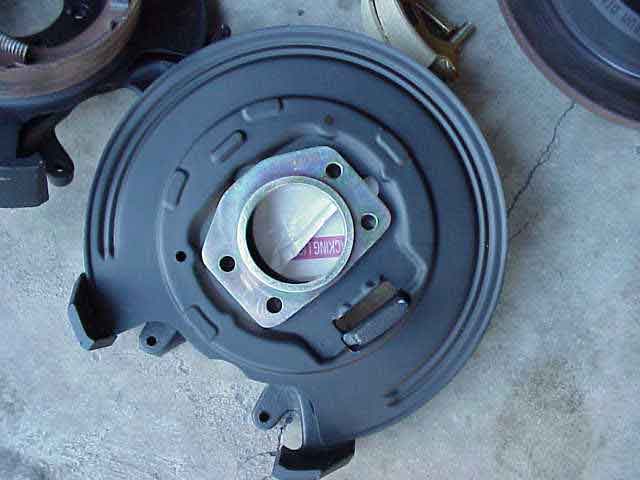
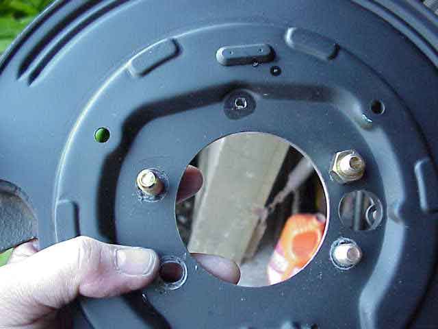
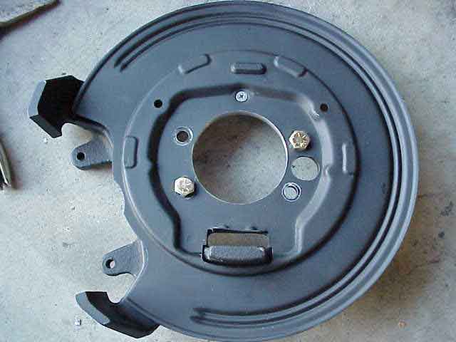
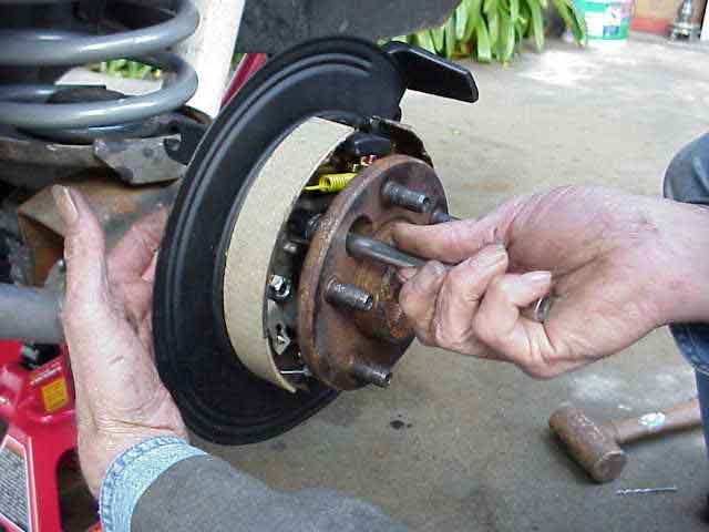
The key ingredient to making this whole thing work, aside from having a buddy that loves to fab TJ projects, was the non-existent axle retainer plate (seen in above pic sitting in the middle of the dust shield.. For this conversion, the retainer plate would anchor the disc caliper bracket to the axle flange. It would also hold the dust shield in place, which in turn holds the parking brake assembly.
It is important to use the new axle retainer, as it is needed to compensate for the thickness difference between the stock backing plate and the thicker cast bracket. It also provides the correct pre-load on the axle bearing that sits at the axle flange. Without a properly fabbed axle retainer plate, this conversion will not work for you.
My SoCal buddy had a few of these manufactured….you know how it is….he knows a friend who does machine work, and then he took them to another friend who did some more work, and then he had them zinc plated, etc. Well, you get the picture.
NOTE: Here are some comments from my buddy in CA who made the retainer plate. He posted this to an on-line forum on 1-13-2003:
I was involved in machining the custom retainers. I saw an ’03 with discs on a lift and noticed that the rear discs on the 44 were identical to the ZJ discs. I wondered how the factory solved the problem and how much it would cost. It’s cheaper that you would ever guess and here are a couple of pics with the part number.
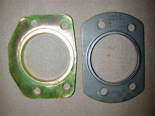
My retainer is shown next to the factory one (factory on the right). The factory part number is 1-05083678AA. Two are required. Cost should be less than 6.00 for both.
NOTE: Another Jeeper forwarded me a note that said his dealership listed the above part # as 5083678AA. It took them a while to find what he wanted using the number previously mentioned. Sounds like a different release of the parts list, or something like that. Anyway, just a heads up that you might find it using either number.
So folks, you can thank the DC engineers for making an inexpensive alternative to the machine custom retainer. While this won’t make anything else any cheaper, it will allow anyone to now go and scour the junk yards for the ZJ parts and stop off at the DC dealership for the “custom part”.
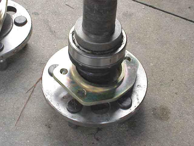
I got four retainer plates….two to convert my main axle shafts and two to convert my trail spares. The above pic shows the new zinc plated retainer plate installed on a D-44 axle shaft. It is located at the bottom of the stack, with the seal, the bearing, and the bearing retainer all sitting on top of it, just as it would be if using the factory back plate. I want to say a big thank you to Jack at CTM Racing Products. Jack was kind enough to let us use his machine shop for a few minutes so we could press on the axle bearings. By the way, check out his site if you are interested in some top quality u-joints for your D-44 or D60 front axle. Some of these recently shipped to a number of ARCA competitors.
The ZJ caliper bracket center hole is just a bit too small to allow the axle seal to pass through it. Just a little bit of metal needs to be removed to allow for proper clearance. This is not a critical measurement. It just needs to let the axle seal slip through without catching. Since the dust shield hole is the same diameter as the bracket hole, it needs to be enlarged as well. It is easy to bolt the dust shield and bracket together with a couple of bolts and then enlarge the “holes” at the same time.
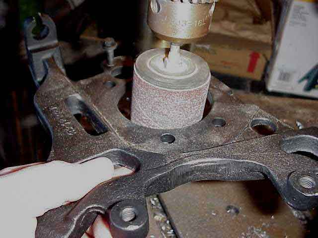
We used a sanding drum that was mounted on the drill press. A couple of minutes and it was ready to go. Use an oil seal to check for adequate clearance. Note that the above photo only shows the bracket, less the dust shield, being worked on. (ok, I admit that I forgot to take the picture while I was actually doing it so I tossed the bracket up there and snapped a picture later in the morning)
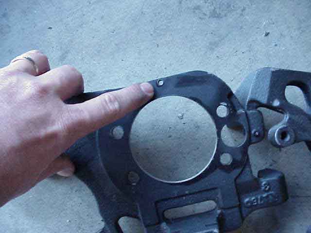
Although not required, my SoCal buddy decided he wanted to make a little modification to the caliper bracket. He drilled and tapped a 10×24 in the bracket. (note the hole just off the end of my finger)
You can see the 10×24 screw in this photo. The end result? Well, when I take out those two bolts that previously held the dust shield and caliper bracket together, the two parts will still be screwed together. It makes it a little bit easier to handle it as an “assembly” when everything stays together easily. Once we start putting the brake shoes and springs on, keeping everything together just makes it easier, especially when you are trying to get everything attached while the axle shaft is being put back into the tube. Note that you do NOT need to do this little modification, but I sure am glad we did.
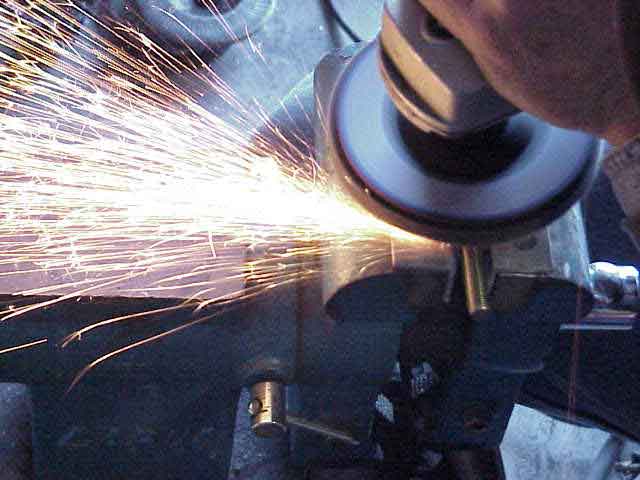
Earlier, I mentioned that we needed some 3/8″ grade 8 bolts. These will be used to secure the retrainer plate and bracket to the end of the axle flange. The factory uses pressed in studs, but these will now be too short and so you will need to remove them. A 1 1/4″ bolt will do the job nicely. In order for it to properly fit at the axle flange, a flat spot on the bolt head was needed. Not too hard when you have the right tool handy.
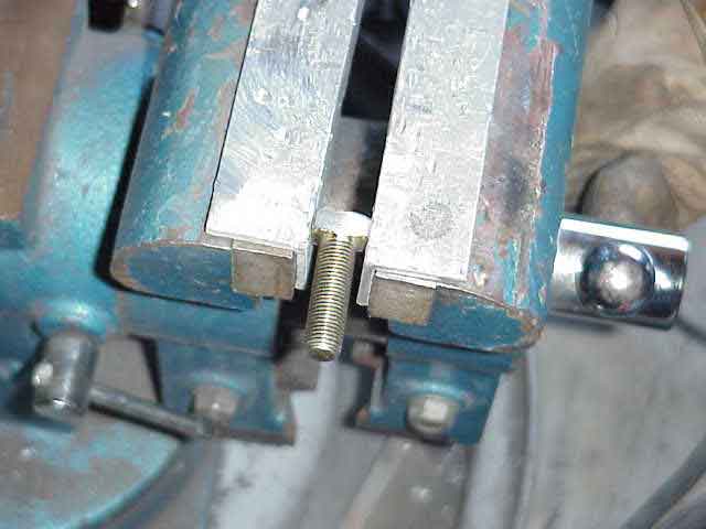
After a few seconds, the bolt has a nice flat spot ground on it. Do the same to the remaining seven bolts. You’ll use four of these bolts on each axle flange, replacing the factory pressed in studs.
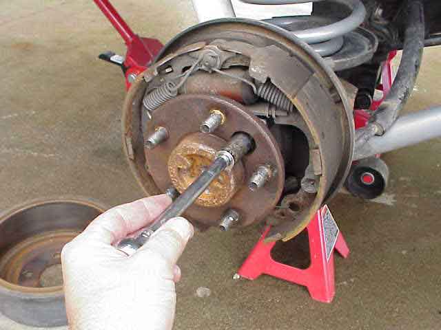
Next, you will need to remove the factory drum brakes. In the picture above, a socket is used to reach the four nuts that hold the factory retainer plate in place. As was suggested to me….”just get the brake shoes and springs and such off”. Since they are not going back on, no biggie in what order you take the stuff apart, as long as you get it all off. None of it will be used for the conversion.
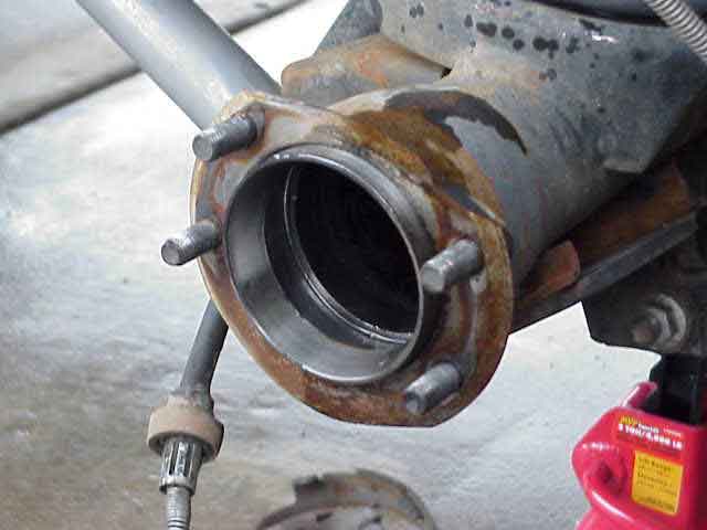
Once you have removed the axle shaft and the brake components, you are left with the four studs in the axle flange.
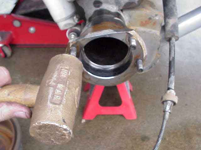
With a brass hammer in hand, a few light taps were all that was needed to pop the studs out of the axle flange.
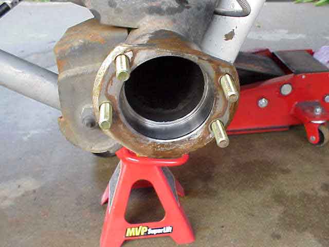
Take four of the 3/8″ grade 8 bolts that you ground a flat spot on slip them into the axle flange. When you do, you will see why you needed to grind a flat spot on the bolt head.
Rear Disc Brake Conversion
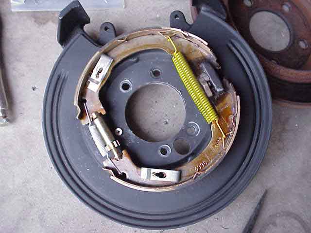
Next, it was time to assemble the e-brake components onto the dust shield. Yours might look a bit different, depending on which shoes you end up with. There are some shoes that can be interchanged between the 8.8 Ford Explorer axle and the Grand Cherokee setup. The ones in this photo happened to be Explorer shoes and springs. We eventually made a little modification to the shoes, where they engage the actuating cam. We also removed the dual top springs and replaced them with a single spring from a Grand Cherokee brake hardware kit. We could have left these in place….it didn’t make much difference.
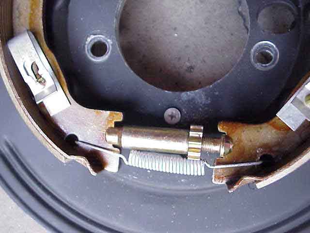
Here is a close up of the brake shoe adjuster….commonly called a “star” adjuster. There is a little rubber plug between the star that can be removed for adjustment access (after the assembly is installed on the vehicle). Note that the spring actually engages the star adjuster and prevents it from moving from vibrations, etc.
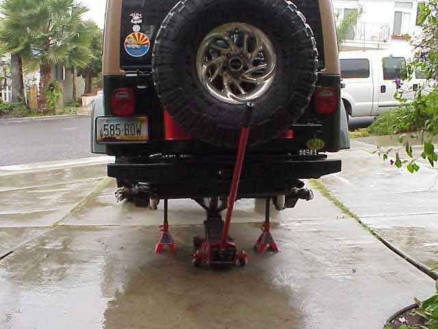
Of course, about the time we need to work on getting things bolted to the end of the axle flange, some rain clouds move in and dampen things up just a bit. It was a bit after noon and we decided now would be a good time to take a break and go find some lunch. “Say, ahhhh…..could we take that white tow rig to the restaurant? I’m thinking the TJ won’t get too far.”
We wrapped up lunch and got back to work (notice the sunshine in the above pic!). We got a little break from the weather and decided to see if we could slip a brake assembly onto the axle. We slipped the bracket over the 3/8″ “studs” we had made and put on some regular nuts, just temporarily, while we checked out how things were fitting together. I should comment here that we did just a little countersink on the 10×24 screw hole that we drilled earlier (at the 6 o’clock position just below the center hole). You don’t want the screw head sticking up and interfering with the retainer plate. Everything must fit nice and flush.

We removed the 10×24 screw from bracket and drilled the hole all the way through the axle flange. You can see the hole being tapped in this pic. This was an easy enough way to handle the excess threads from the screw that were sticking out of the back of the caliper bracket. It only took a minute to do and worked just fine. You can also see the new e-brake cable in the above photo. It is not yet attached to the back of the caliper bracket. When the 10×24 screw is put back in and the four temporary nuts are removed from the studs, everything would get a little loose while attempting to put the axle shaft back into place. You can see why this little screw is so handy.
Rear Disc Brake Conversion
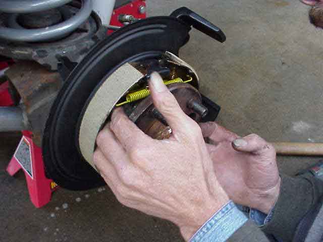
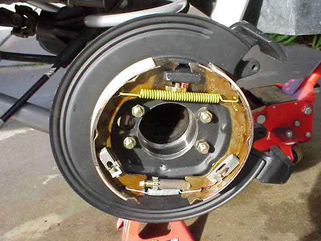
Next, we slipped the axle shaft into the housing, after removing the 4 temporary nuts we had put on earlier. Be careful when sliding the seal through the hole in the center of the dust shield (this was the part you enlarged earlier).
Line up the new retainer plate over the four studs (those bolts that you ground a flat spot on) and put on the upset lock nuts. In this picture, we are getting the nuts started by hand using a socket and extension. Unlike the factory studs, you need to keep a finger on the back side of the bolt head until you got the nut started. The bolt will not rotate because of its close proximity to the axle tube.
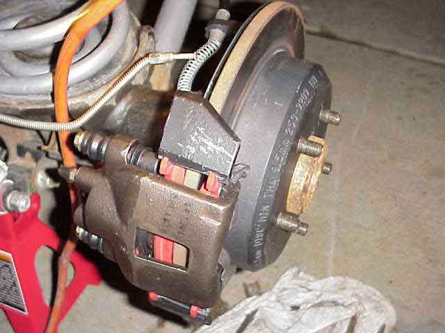
I apologize for switching sides here. I forgot to snap a picture after we got the axle shaft in and bolted down. We slipped on the rotor and the caliper (with pads).
Note: Switching from drum brakes to disc brakes will cause the wheel stud to be a bit shorter than desired. There are two ways to handle this…..use extended thread lug nuts or press out the old wheel studs and replace them with some longer ones. Dorman P/N 610-368 are reported to be slightly longer and will work well with the conversion. Since ’03, TJs could be had with factory rear disc brakes. As such, the wheel stud used on these models could be used also. The DC part number is 1-04762841 (which was confirmed via e-mail by a Jeeper that purchased them from his local Jeep dealership). The DC lugs are 1/4″ longer than the stock lugs (making them 1 7/8″ in length).
The only thing left to do here is to plumb in the brake line. The e-brake cable has also been attached to the back of the bracket.
If you haven’t done double flared brake line connections, I would suggest getting hold of someone who has and invite them to come over with their flaring toolbox. Although I didn’t ask, I suspect that a quality flaring tool for steel brake lines costs a few bucks. I was lucky that my SoCal buddy had both the tools and the skill to do a very nice job on my brake lines. Now that I’ve seen the little tricks for making a nice double flare connection, I think I could crank one out given a couple of practice runs on a scrap piece of brake line.
Note: Since this write-up was completed, I’ve had the opportunity to do a couple of brake line flares. I used a rented flaring tool from AutoZone. They have a variety of tools that they will rent for free (you have to provide them with a refundable deposit) and I’ve used a few of them (pitman arm puller, power steering pulley remover, flaring tool, spring compressor, etc.)
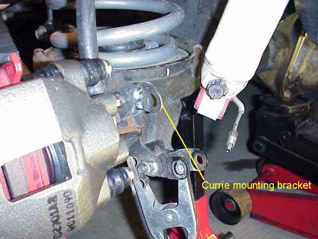
Once we had the steel line cut and flared, my buddy welded on a nice little bracket that comes as part of a brake mounting kit from Currie Enterprises. I have to give some praise here to Currie….that little kit had everything we needed to transition the brake line from steel to rubber hose. The mounting bracket was even cut to fit the curve of the D-44 tubes. When you call Currie at 714-528-6957, ask for the Ford Explorer Rear Disc Brake Conversion Hose Kit. The part number is #6013 and runs under $40.
The kit contains the clips to weld to the axle tubes, clips for them, hoses, banjo bolts, and copper sealing washers both rear brakes.
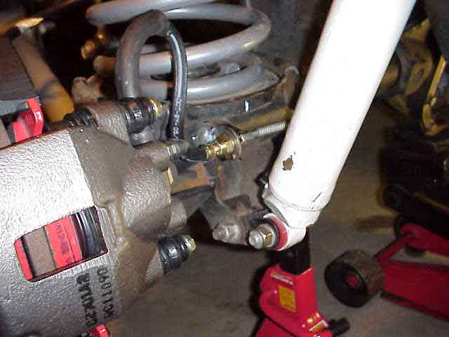
Here is the completed brake line interface with everything hooked up and back in place. I gotta remember to hit that new bracket with a bit of flat black paint so it won’t rust.
And a close up shot of the mounting bracket and the retainer clip that is provided with the flexible hose in the Currie kit.
NOTE: I received an e-mail from Robert Murphy which contained some info that I’ll pass along for all to benefit from.
He said….“Instead of the Currie brake hoses, you can use Mopar Part # 52128430AC and 52158431AB. These are the hoses for the disc brake rear axle on a TJ, and include a bolt on bracket that mounts on the spring perch, and the hard tube that goes all the way to the factory T fitting on the hose coming from the frame. They are obviously for a D44, but can be reshaped to work on the D35 if needed. This eliminates the need for welding the retainer bracket on, and double flaring the brake tubing. This makes it a bolt on proposition.”
Rear Disc Brake Conversion
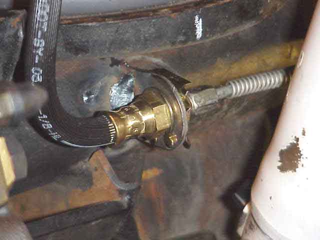
After both rear calipers were on and the brake lines were attached, we pulled the combination/proportioning valve and removed the small black o-ring from the stem and then buttoned it back up. Be careful when removing the threaded cap, since there is a spring inside which keeps it under tension. If you have a friend near by, solicit some help as it is much easier to reassemble this with two people working on it.
NOTE: As of February, 2003, I installed a new ZJ combination valve in place of the TJ’s valve. The details can be seen here.
The other item we had to take care of was the installation of the new Performance Friction pads for the front calipers. These pads, available from AutoZone, are a necessary part of this conversion. The Performance Friction pads improve the front calipers performance. It seems to keep the bias between the front and rear calipers balanced out so that the installed changes still work well together. A quick brake bleeding session got the air out of the lines.
The last thing to do before picking up the tools was to break in the Performance Friction pads. This consists of a series (about 10) of rapid braking stops from about 40 MPH down to a full stop. After the first round of ten, drive around and let the rotors cool down a bit. After 5 minutes or so of no or low braking effort, repeat the rapid stopping sequence another 10 times. During this entire process, you should notice the braking performance improves as the Performance Friction pads are broken in.
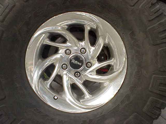
Well, there it is. Disc brakes peaking out between the spokes of my rear rim. I love the performance change I’ve experienced so far. This is one mod that I couldn’t have done without my SoCal buddy (and Robert’s back bedroom to crash in for a few days). A big thanks to both of them.
Note: If you find your wheel studs are a bit short, check this out for a possible solution.
Note: I pulled the following comment from an on-line forum where a friend of mine had just posted about the successful completion of his rear disc conversion. He said:
“I used a set (disc brakes) from a ’98 Grand with a D44A, not a D35. Everything went according to plan and the results seem to be well worth the effort. Hopefully I can get the TJ on a trail next weekend and really see how they perform. All procedures were identical to using a set of discs off a D35c.”
Parts List and Prices
Note: The following list of parts was passed on to me from Rick E. from Spokane, Washington. Rick did the disc brake conversion on his ’98 TJ.
| Item | Part Number | Vendor | Price | # Needed | Total | Vehicle | Year | Comments |
| Axle bearings | Set 10 Timken | NAPA | $ 25.91 | 2 | $ 51.82 | TJ Wrangler | 1998 | |
| Axle seal Dana 44 | 18731 | NAPA | $ 9.79 | 2 | $ 19.58 | TJ Wrangler | 1998 | |
| Bearing retainers | NA | Mr. Blaine | $ 45.00 | 1 | $ 45.00 | TJ Wrangler | 1998 | Rubicon part number |
| Brake tube, hose, and mount — Left side | 52128431AC | Jeep Dealer | $ 16.50 | 1 | $ 16.50 | TJ Rubicon | 2003 | |
| Brake tube, hose, and mount — Right side | 52128430AC | Jeep Dealer | $ 18.92 | 1 | $ 18.92 | TJ Rubicon | 2003 | |
| Disk Brake Caliper | ? | Wrecking yard | $20 | 2 | $ 40.00 | Ford Explorer | 95-’01 | Came rebuilt with new pads. |
| Disk Brake Rotor | 4886565 | NAPA | $ 36.98 | 2 | $ 73.96 | Ford Explorer | 95-’01 | Should have used one from a Grand-thinner flange at axle than Explorer. Short wheel studs. |
| Emergency Brake Cables | ? | Wrecking yard | $20 | 2 | $ 40.00 | Grand Cherokee | 95-’98 | Can use Rubicon as well. |
| Grade 8 bolts — 8 total | NA | Hardware store | $ 8.00 | 1 | $ 8.00 | |||
| Loaded Backing Plate–e-brake Left side | 52128414AB | Jeep Dealer | $ 64.46 | 1 | $ 64.46 | TJ Rubicon | 2003 | |
| Loaded Backing Plate–e-brake Right side | 52128415AB | Jeep Dealer | $ 64.46 | 1 | $ 64.46 | TJ Rubicon | 2003 | |
| Mounting bolt kit, Caliper to Mounting plate | 83177 | NAPA | $ 8.99 | 2 | $ 17.98 | Ford Explorer | 95-’01 | |
| Proportioning Valve | ? | Wrecking yard | $ 16.00 | 1 | $ 16.00 | Grand Cherokee | 95-’98 | With 4 wheel disk brakes. Used one from a ’95 which has same electrical connection. |
| T-fitting for proportioning valve | 7900 | NAPA | $ 5.26 | 1 | $ 5.26 | NA | ||
| $ 430.12 | ||||||||
| Other useful parts | ||||||||
| Rear disk brake hardward kit | NAPA | 1 | Grand Cherokee | 95-’98 | Springs, pins, adjusters, etc. If rebuilding Grand Cherokee rear disk brakes. | |||
| Rear brake pads | NAPA | 1 | Grand Cherokee | 95-’98 | ||||
| Bearing retainers Dana 44 | Jeep Dealer | 2 | TJ Rubicon | 2003 | ||||
Installing a ZJ Combination Valve
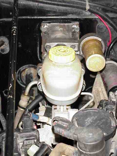
In February, 2002, I finally swapped out the TJ combination valve and installed one from a ZJ, part number 52009061AB. While not overly difficult to do, I thought I would include a couple of photos from the swap. Many thanks to Les for stopping by to help with this swap.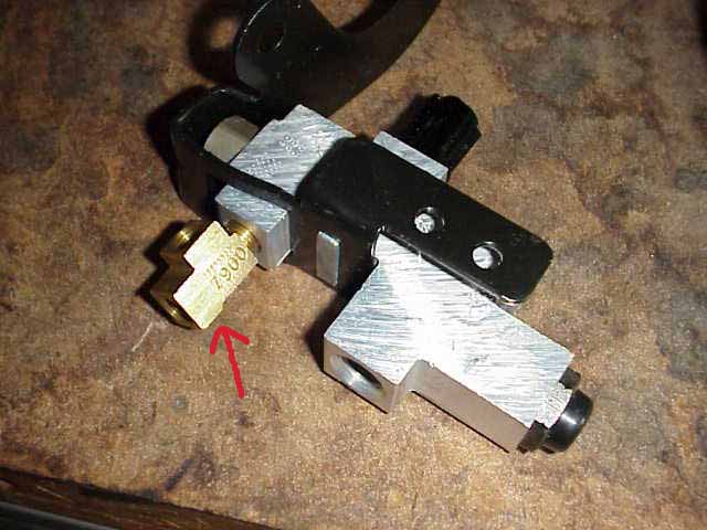
I ordered the ZJ combination valve from a local DC dealership ($50). Note that the brass t-fitting shown in the above picture (the red arrow) does NOT come with the new combination valve. I picked it up at the local NAPA store for $7. The t-fitting part number, as can be seen above, is 7900. They had a handful of them in the brake parts drawer so it appears that this is not a difficult item to find. (of course, the “dude” at the local Checker auto store told me I would never find one!) The combination valve comes with the bracket attached to the valve. It appears to be stamped onto the valve body. The bracket is not quite the same as the one used on the TJ….some minor bending is needed to get everything to line up.
Note: This comment is being added after the work and write-up were completed. I believe there is a way to mount the original TJ bracket on the ZJ valve body. Doing so would have simplified the install since the only install issue was that of getting the hard lines to bend a bit and line up with the ports on the valve body.
Here is the TJ combination valve. You can see the slight difference in the mounting bracket. The t-fitting is needed because the ZJ combination valve does not have the 2nd output port at the back of the valve body like the TJ does in the above picture.
Grab a couple of rags to soak up the brake fluid while you do the swap. It isn’t too bad….one of the two lines from the master cylinder drips brake fluid once you disconnect the metal lines from the combination valve.
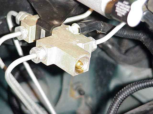
Here is the ZJ valve installed. By now, you will have noticed that the electrical connector for the pressure differential switch (in the valve body) is not the same as the one you have on your TJ harness. The differential switch monitors fluid pressure in the separate front / rear brake hydraulic circuits. A decrease or loss of fluid pressure in either circuit will cause the switch to activate the BRAKE light on the instrument cluster. I’ve not changed mine yet. My plans are for obtaining a ZJ connector from the local junk yard and then cutting off the TJ connector so I may splice the ZJ connector into the harness. I can detect no other problem with having the connector removed, other than the operation of the BRAKE light in the dash.
The last step was to bleed the brakes. Les and I did a full bleed at all 4 calipers and then took it for a test drive. The peddle still felt soft and I was not able to lock up the brakes. We returned home and did another bleeding session. That one went better.
You may be wondering why I swapped the combination valves after having run the o-ring modification for more than a year. One thing I noticed, since the disc brake conversion, was that my rear wheels were abnormally warm (compared to the front wheels). This was more prevalent in the warmer months when the air temp did little to help dissipate the heat. It is my assumption that the TJ combination valve, which was designed for rear drum brakes, was keeping several pounds of residual pressure (normal for drum brakes) on the rear calipers and thus causing just a little bit of friction induced heat. I could be all wrong about this….time will tell as the summer approaches. Regardless, the ZJ combination valve is designed for disc brakes front and rear. The only question now is if the weight difference (between a ZJ and a TJ) will cause any front to rear bias issues for braking pressures.
So….how does it feel after the swap?. Pretty good….so far. I’ve only taken it down to get some fast food since installing it this morning. I’ll update this in a few weeks or months once I get a chance to really test the brakes. (I did notice that I could lock up the 35″ MT/Rs on the way to McDonalds. The roads were a little damp from last nights weather so I won’t say this was good or bad…..I still need some more behind the wheel time.)
TJ Hydro-Boost
Robert Yates got together with Blaine Johnson (both wheelin’ friends of mine from SoCal) to address Robert’s desire to have better brakes on his 35″ tired TJ. During my last visit to Robert’s place (Blaine was helping me relocate my rear shocks), I stuck my head under the TJ’s hood to take a look at what they came up with. I snapped a few pictures and asked Robert to write up a description so the rest of you could get an idea that some folks go just a bit further when it comes to restoring good braking performance on their TJ. Here is what Robert had to say about the hydro-boost project on his TJ. (Thanks to Robert and Blaine for sharing this good information!)
Background:
The Jeep is using the stock master, prop. valve, stock front brakes (using Performance Friction pads) and has a ZJ rear disc brake conversion with the o-ring in the prop valve removed. The Jeep still utilizes the stock power steering pump and box, with the steering links still in the stock design parameter, ie no high steer or trackbar locational changes.
While the rear disc brake conversion was an improvement and generally acceptable, pedal feel was spongy at best and required a vigorous amount of leg pressure in a hard stop situation. The Jeep also runs a TeraLow with an automatic transmission so brake performance in off road/rockcrawling situations required improvement as well. On steep downhill crawling situations (such as a drop off a ledge or waterfall) the TJ in some instances, would require a shift into neutral to recover braking power as the t-case and automatic transmission would “push” the Jeep by outrunning braking capability.
The intent of adding the hydro-boost was to provide for a firmer pedal feel, while obtaining additional braking performance by adding more line pressure than what was being achieved with the stock vacuum booster.
Hydro-boost & Adaption for Use:
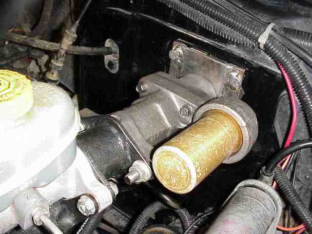
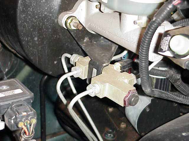
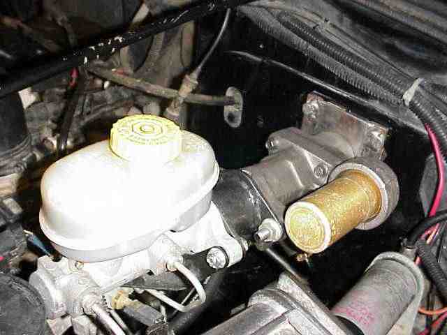
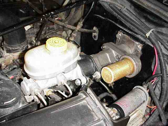
The hydro-boost unit was sourced from a 1 ton Chevy truck application. Delivery of the unit revealed that modifications would have to be dealt with in order for the hydro-boost to accept the stock master cylinder rod as well as for mounting it on the firewall.
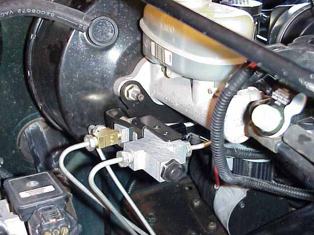
Accordingly, a flanged adapter was constructed (painted gray Hammerite and seen in pictures below) which would mount to the TJ master and accept the rod, and a firewall mounting bracket to adapt the different bolt pattern of the hydro-boost to the TJ firewall. Also required was a simple rod extension for the hydro-boost to actuate the master.
Lastly, the pedal rod on the hydro-boost unit was shortened in order to land the brake pedal in a reasonably close to stock position inside the cabin.
Installation:
Installation was relatively straight forward once the fabrication of the adapter and bracket was completed – taking approximately 5 hours for the hydro-boost unit itself.
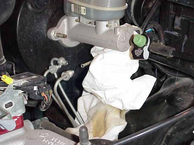
Initial disassembly included unbolting the master from the stock vacuum booster along with disassembly of the brake pedal rod inside the cabin. It should be noted that at no time were any brake lines opened thus no re-filling of the master or bleeding of the brake system occurred.
Additionally, the combination of the length of the hydro-boost with the flanged adapter, required that some of the EVAC components located on the fender be moved to accommodate the longer length of the hydro-boost assembly, thus the fender mounted bracket was also unbolted (see first picture and use as comparison to stock to see where EVAC was reoriented).
Since the hydro-boost utilizes the power steering pump as opposed to the vacuum booster to provide braking assist, it requires high and low pressure hoses to be constructed and plumbed into the Jeep. High quality Firestone line along with barbed hydraulic fittings were used throughout. The installation of the hydro-boost unit also included plumbing in a stacked plate style Hayden power steering cooler inside the grill in front of the a/c condenser. This added about 3 more hours to the overall installation time.
Initially, the stock power steering hoses were all removed and the intent was to install all new hose for each connection. Trying to plumb in a “tee” off the top of the stock pump for the hydro-boost high pressure line (pump to hydro-boost) proved to be difficult and in looking at the situation, it occurred to us that the stock high pressure line (from the pump to steering box) could be flipped over and reused for the pump to hydro-boost connection. This will save both time and money and I like the idea of re-using stock parts if possible.
The remainder of the lines were then constructed with time taken to route hose and orient fittings so that no interference issues would occur. The power steering system then required new fluid to be added (I used Valvoline Syntech) and the entire system was bled to remove air.
Results:
The difference in braking power was dramatic. While I do not yet have any scientific data, such as a line pressure comparison, it is clear from a seat of the pants perspective that braking power has been greatly enhanced. The pedal is now quite firm and it is possible to lock up all 4 tires in a controlled fashion, ie. the fronts lock up first and then the rears. I did fiddle with tire pressure a bit, running 2psi more in the rears than the fronts to further enable good proportional response.
My stock power steering pump has over 67k miles on it and while it has so far stood up to the additional stress of the hydro-boost unit, I plan to eventually swap in an aftermarket pump with remote reservoir. This will add both braking power as well as steering power in the rocks so in consideration of the steering, it probably would have happened anyways and is not absolutely necessary to the success of the hydro-boost modification.